HFBR-2526ETZ Avago Technologies US Inc., HFBR-2526ETZ Datasheet
HFBR-2526ETZ
Specifications of HFBR-2526ETZ


Related parts for HFBR-2526ETZ


HFBR-2526ETZ Summary of contents
Page 1
... Hard Clad Silica (HCS ) fiber. With the recom mended drive circuit, the LED operates at speeds from 1-125 MBd. The HFBR-2526ETZ is a high band width analog receiver con- tain ing a PIN photodiode and internal transimpedance amplifier. With the recommended applica tion circuit for ...
Page 2
... Run length limited code with maximum run length of 10 Ps. 3. Minimum link performance is projected based on the worst case specifications of the HFBR-1527ETZ transmitter, HFBR-2526ETZ receiver, and POF cable, and the typical performance of other components (e.g. logic gates, transistors, resistors, capacitors, quantizer, HCS cable). ...
Page 3
... Average Modulated Power = 3. High and low level LED currents refer to the current through the HFBR-1527ETZ LED. The low level LED “off” current, sometimes referred to as “hold-on” current, is prebias supplied to the LED during the off state to facilitate fast switching speeds. ...
Page 4
... Plastic and Hard Clad Silica Optical Fiber Receiver Application Circuit [4] Performance of the HFBR-2526ETZ receiver in the recommended application circuit (Figure 1); 1-125 MBd, 25° C unless otherwise stated. Parameter Data Output Voltage – Low Data Output Voltage – High Receiver Sensitivity to Average Modulated Optical Power 1 mm POF ...
Page 5
V ECL SERIAL DATA SOURCE 0 0 0 ECL SERIAL DATA RECEIVER 120 120 Figure 2. Recommended power supply filter and +5 ...
Page 6
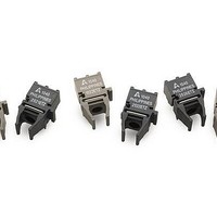
... LED in a horizontal (HFBR-1527ETZ) gray housing. The HFBR-1527ETZ transmitters are suitable for use with current peaking to decrease response time and can be used with HFBR-2526ETZ receivers in data links operating at signal rates from 1 to 125 megabaud over 1 mm diameter plastic optical fiber or 200 Pm diameter hard clad silica glass optical fiber ...
Page 7
... Optical power measured at the end of either 0.5m of 1mm diameter POF (NA=0. 200 um diameter HCS (NA=0.37) with a large area detector. 4. Typical value measured from junction to PC board solder joint for horizontal mount package, HFBR-1527ETZ. 5. Optical rise and fall times can be reduced with the appropriate driver circuit. ...
Page 8
HP8082A PULSE BCP MODEL 300 GENERATOR 500 MHz BANDWIDTH SILICON AVALANCHE PHOTODIODE 50 W HP54002A 50 W BNC LOAD OSCILLOSCOPE INPUT POD RESISTOR Figure 5. Test circuit for measuring unpeaked rise and fall times 2.4 -40 2 2.2 ...
Page 9
... Description The HFBR-2526ETZ receivers contain a PIN photodiode and transimpedance pre-amplifier circuit in a horizontal (HFBR-2526ETZ) blue housing, and are designed to inter- face diameter plastic optical fiber or 200 Pm hard clad silica glass optical fiber. The receivers convert a received optical signal to an analog output voltage. ...
Page 10
Electrical/Optical Characteristics -40 to 85° C; 5.25 V ≥ V Parameter AC Responsivity 1 mm POF AC Responsivity 200 μm HCS RMS Output Noise Equivalent Optical Noise Input Power, RMS – POF Equivalent Optical Noise Input Power, RMS ...
Page 11
... HFBR-25X6ETZ Figure 9. Recommended power supply filter circuit Figure 10. Simplified receiver schematic Figure 11. Typical pulse width distortion vs. peak input power 11 Figure 12. Typical output spectral noise density vs. frequency Figure 13. Typical rise and fall time vs. tempera- ture ...
Page 12
... No internal connection ** Pins 5 and 8 connected internally to each other only. www.avagotech.com 7.62 (0.300) 1.01 (0.040) DIA 7.62 (0.300) PCB EDGE 5 8 1.85 MIN. (0.073) Transmitters Receivers HFBR-1527ETZ HFBR-2526ETZ ANODE SIGNAL CATHODE GROUND GROUND* GROUND GROUND* VCC (+5 V) GROUND** GROUND** GROUND** GROUND** ...