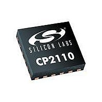
CP2110-F01-GM Silicon Laboratories Inc, CP2110-F01-GM Datasheet - Page 14

CP2110-F01-GM
Manufacturer Part Number
CP2110-F01-GM
Description
IC HID USB-TO-UART BRIDGE 24QFN
Manufacturer
Silicon Laboratories Inc
Specifications of CP2110-F01-GM
Package / Case
24-WFQFN Exposed Pad
Applications
UART-to-USB Bridge
Interface
UART, USB
Voltage - Supply
1.8V, 3 V ~ 3.6 V
Mounting Type
Surface Mount
Input Voltage Range (max)
3.6 V
Maximum Operating Temperature
+ 85 C
Minimum Operating Temperature
- 40 C
Mounting Style
SMD/SMT
Operating Supply Voltage
3.3 V
Supply Current (max)
18.5 mA
Lead Free Status / RoHS Status
Lead free / RoHS Compliant
For Use With
336-2003 - KIT EVAL FOR CP2110
Lead Free Status / Rohs Status
Lead free / RoHS Compliant
Other names
336-2006-5
Available stocks
Company
Part Number
Manufacturer
Quantity
Price
Company:
Part Number:
CP2110-F01-GM
Manufacturer:
ST
Quantity:
12 000
Part Number:
CP2110-F01-GMR
Manufacturer:
SILICON LABS/芯科
Quantity:
20 000
CP2110
6. Asynchronous Serial Data Bus (UART) Interface
The UART interface consists of the TX (transmit) and RX (receive) data signals as well as the optional RTS and
CTS flow control signals. The UART is programmable to support a variety of data formats and baud rates. The data
format and baud rate are set during device configuration on the PC. The data formats and baud rates available to
each interface are listed in Table 10.
The baud rate generator for the UART interface is very flexible and allows the user to request any baud rate in the
range from 300 bps to 1 Mbps. If the baud rate cannot be directly generated from the internal 24 MHz oscillator, the
device will choose the closest possible option. The actual baud rate is dictated by Equation 1 and Equation 2.
Most baud rates can be generated with an error of less than 1.0%. A general rule of thumb for the majority of UART
applications is to limit the baud rate error on both the transmitter and the receiver to no more than ±2%. The clock
divider value obtained in Equation 1 is rounded to the nearest integer, which may produce an error source. Another
error source will be the 24 MHz oscillator, which is accurate to ±0.25%. Knowing the actual and requested baud
rates, the total baud rate error can be found using Equation 3.
The UART also supports the transmission of a line break. The length of time for a line break is programmable from
1 to 125 ms, or it can be set to transmit indefinitely until a stop command is sent from the application.
14
Clock Divider
Actual Baud Rate
=
----------------------------------------------------------------------------------------------------
2 Prescale
Notes:
Parity Type None, Even, Odd, Mark, Space
Baud Rate
Stop Bits
Data Bits
1. 1.5 stop bits only available when using 5 data bits.
2. Baud rates above 500,000 baud not supported with 5 or 6 data bits.
=
Baud Rate Error (%)
---------------------------------------------------------------------------- -
2
Prescale Clock Divider
Table 10. Data Formats and Baud Rates
Equation 3. Baud Rate Error Calculation
24 MHz
Requested Baud Rate
Equation 1. Clock Divider Calculation
5, 6, 7, and 8
1, 1.5
300 bps to 1 Mbps
24 MHz
Equation 2. Baud Rate Calculation
1
, and 2
=
100
Rev. 1.0
1
–
2
---------------------------------------------------------- -
Requested Baud Rate
Prescale
Prescale
Actual Baud Rate
Prescale
Prescale
=
=
=
=
4 if Requested Baud Rate 300 bps
1 if Requested Baud Rate 300 bps
4 if Requested Baud Rate 300 bps
1 if Requested Baud Rate 300 bps
0.25%


