EFM32G890F64 Energy Micro, EFM32G890F64 Datasheet - Page 176
EFM32G890F64
Manufacturer Part Number
EFM32G890F64
Description
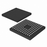
MCU 32BIT 64KB FLASH 112-BGA
Manufacturer
Energy Micro
Series
Geckor
Datasheets
1.EFM32-G890F128-SK.pdf
(70 pages)
2.EFM32-G890F128-SK.pdf
(10 pages)
3.EFM32G200F16.pdf
(463 pages)
4.EFM32G200F16.pdf
(136 pages)
Specifications of EFM32G890F64
Core Processor
ARM® Cortex-M3™
Core Size
32-Bit
Speed
32MHz
Connectivity
EBI/EMI, I²C, IrDA, SmartCard, SPI, UART/USART
Peripherals
Brown-out Detect/Reset, DMA, LCD, POR, PWM, WDT
Number Of I /o
90
Program Memory Size
64KB (64K x 8)
Program Memory Type
FLASH
Ram Size
16K x 8
Voltage - Supply (vcc/vdd)
1.8 V ~ 3.8 V
Data Converters
A/D 8x12b, D/A 2x12b
Oscillator Type
External
Operating Temperature
-40°C ~ 85°C
Package / Case
112-LFBGA
Processor Series
EFM32G890
Core
ARM Cortex-M3
Data Bus Width
32 bit
Data Ram Size
16 KB
Interface Type
I2C, UART
Maximum Clock Frequency
32 MHz
Number Of Programmable I/os
90
Number Of Timers
3
Operating Supply Voltage
1.8 V to 3.8 V
Maximum Operating Temperature
+ 85 C
Mounting Style
SMD/SMT
Minimum Operating Temperature
- 40 C
Lead Free Status / RoHS Status
Lead free / RoHS Compliant
Eeprom Size
-
Lead Free Status / Rohs Status
Details
Available stocks
Company
Part Number
Manufacturer
Quantity
Price


16.3 Functional Description
16.3.1 Modes of Operation
2010-09-06 - d0001_Rev1.00
• Configurable number of data bits, 4-16 (plus the parity bit, if enabled)
• Configurable number of stop bits in asynchronous mode: 0.5, 1, 1.5, 2
• HW collision detection
• Multi-processor mode
• IrDA modulator on USART0
• SmartCard (ISO7816) mode
• Separate interrupt vectors for receive and transmit interrupts
• Loopback mode
An overview of the USART module is shown in Figure 16.1 (p. 176) .
Figure 16.1. USART Overview
The USART operates in either asynchronous or synchronous mode.
In synchronous mode, a separate clock signal is transmitted with the data. This clock signal is generated
by the bus master, and both the master and slave sample and transmit data according to this clock.
Both master and slave modes are supported by the USART. The synchronous communication mode is
compatible with the Serial Peripheral Interface Bus (SPI) standard.
In asynchronous mode, no separate clock signal is transmitted with the data on the bus. The USART
receiver thus has to determine where to sample the data on the bus from the actual data. To make this
possible, additional synchronization bits are added to the data when operating in asynchronous mode,
resulting in a slight overhead.
• HW parity bit generation and check
• Half duplex communication
• Communication debugging
U(S)n_RX
U(S)n_TX
USn_CLK
USn_CS
Pin
ctrl
UART Control
and status
m odulator
IrDA
dem odulator
...the world's most energy friendly microcontrollers
TX Shift Register
Peripheral Bus
IrDA
176
(2-level FIFO)
TX Buffer
Baud rate
generator
RX Shift Register
(2-level FIFO)
RX Buffer
www.energymicro.com
! RXBLOCK
Related parts for EFM32G890F64
Image
Part Number
Description
Manufacturer
Datasheet
Request
R

Part Number:
Description:
KIT STARTER EFM32 GECKO
Manufacturer:
Energy Micro
Datasheet:

Part Number:
Description:
KIT DEV EFM32 GECKO LCD SUPPORT
Manufacturer:
Energy Micro
Datasheet:

Part Number:
Description:
BOARD PROTOTYPING FOR EFM32
Manufacturer:
Energy Micro
Datasheet:

Part Number:
Description:
KIT DEVELOPMENT EFM32 GECKO
Manufacturer:
Energy Micro
Datasheet:

Part Number:
Description:
MCU, MPU & DSP Development Tools TG840 Sample Kit
Manufacturer:
Energy Micro
Datasheet:

Part Number:
Description:
MCU, MPU & DSP Development Tools TG Starter Kit
Manufacturer:
Energy Micro
Datasheet:
Part Number:
Description:
MCU, MPU & DSP Development Tools TG108 Sample Kit
Manufacturer:
Energy Micro
Part Number:
Description:
MCU, MPU & DSP Development Tools TG210 Sample Kit
Manufacturer:
Energy Micro
Datasheet:
Part Number:
Description:
MCU, MPU & DSP Development Tools TG822 Sample Kit
Manufacturer:
Energy Micro
Datasheet:
Part Number:
Description:
MCU, MPU & DSP Development Tools TG230 Sample Kit
Manufacturer:
Energy Micro

Part Number:
Description:
SAMPLE KIT (SMALL BOX - CONTAINING 2 DEVICES)
Manufacturer:
Energy Micro
Part Number:
Description:
SAMPLE KIT (SMALL BOX - CONTAINING 2 DEVICES)
Manufacturer:
Energy Micro