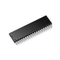
AT89LP52-20PU Atmel, AT89LP52-20PU Datasheet - Page 30

AT89LP52-20PU
Manufacturer Part Number
AT89LP52-20PU
Description
IC MCU 8051 8K FLASH SPI 40PDIP
Manufacturer
Atmel
Series
89LPr
Datasheet
1.AT89LP52-20MU.pdf
(113 pages)
Specifications of AT89LP52-20PU
Core Processor
8051
Core Size
8-Bit
Speed
20MHz
Connectivity
EBI/EMI, I²C, SPI, UART/USART
Peripherals
Brown-out Detect/Reset, POR, PWM, WDT
Number Of I /o
36
Program Memory Size
8KB (8K x 8)
Program Memory Type
FLASH
Ram Size
256 x 8
Voltage - Supply (vcc/vdd)
2.4 V ~ 5.5 V
Oscillator Type
Internal
Operating Temperature
-40°C ~ 85°C
Package / Case
40-DIP (0.600", 15.24mm)
Processor Series
AT89x
Core
8051
Data Bus Width
8 bit
Data Ram Size
256 B
Interface Type
Serial
Maximum Clock Frequency
20 MHz
Number Of Programmable I/os
36
Number Of Timers
3
Operating Supply Voltage
2.7 V to 5.5 V
Maximum Operating Temperature
+ 85 C
Mounting Style
Through Hole
Lead Free Status / RoHS Status
Lead free / RoHS Compliant
Eeprom Size
-
Data Converters
-
Lead Free Status / Rohs Status
Details
6.4
Table 6-2.
Note:
30
TPS[3-0]
CDV[2-0]
Symbol
CLKREG = 8FH
Not Bit Addressable
Bit
System Clock Divider
The reset value of CLKREG is 0000000B in Fast mode and 01010010B in Compatibility mode.
AT89LP51/52 - Preliminary
Function
Timer Prescaler. The Timer Prescaler selects the time base for Timer 0, Timer 1, Timer 2 and the Watchdog Timer. The
prescaler is implemented as a 4-bit binary down counter. When the counter reaches zero it is reloaded with the value
stored in the TPS bits to give a division ratio between 1 and 16. By default the timers will count every clock cycle in Fast
mode (TPS = 0000B) and every six cycles in Compatibility mode (TPS = 0101B).
System Clock Division. Determines the frequency of the system clock relative to the oscillator clock source.
CDIV2
0
0
0
0
1
1
1
1
CLKREG
TPS3
7
– Clock Control Register
CDIV1
0
0
1
1
0
0
1
1
The CDV
source by powers of 2. The clock divider provides users with a greater frequency range when
using the Internal Oscillator. For example, to achieve a 230.4 kHz system frequency when using
the RC oscillator, CDV
be used to reduce power consumption by decreasing the operational frequency during non-criti-
cal periods. The resulting system frequency is given by the following equation:
where f
for the CPU and all peripherals. The value of CDV may be changed at any time without interrupt-
ing normal execution. Changes to CDV are synchronized such that the system clock will not
pass through intermediate frequencies. When CDV is updated, the new frequency will take
affect within a maximum period of 32 x t
In Compatibility mode the divider defaults to divide-by-2 and and in Fast mode it defaults to no
division.
TPS2
6
OSC
CDIV0
0
1
0
1
0
1
0
1
2-0
is the frequency of the selected clock source. The clock divider will prescale the clock
bits in CLKREG allow the system clock to be divided down from the selected clock
TPS1
5
System Clock Frequency
f
f
f
f
f
f
Reserved
Reserved
OSC
OSC
OSC
OSC
OSC
OSC
/1
/2
/4
/8
/16
/32
2-0
should be set to 011B for divide-by-8 operation. The divider can also
TPS0
4
OSC
CDV2
f
SYS
.
3
=
------------ -
2
f
OSC
CDV
CDV1
2
Reset Value = 0?0? 00?0B
CDV0
1
3709B–MICRO–12/10
—
0


