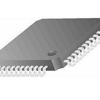
AT89LP52-20AU Atmel, AT89LP52-20AU Datasheet - Page 54

AT89LP52-20AU
Manufacturer Part Number
AT89LP52-20AU
Description
IC MCU 8051 8K FLASH SPI 44TQFP
Manufacturer
Atmel
Series
89LPr
Datasheet
1.AT89LP52-20MU.pdf
(113 pages)
Specifications of AT89LP52-20AU
Core Processor
8051
Core Size
8-Bit
Speed
20MHz
Connectivity
EBI/EMI, I²C, SPI, UART/USART
Peripherals
Brown-out Detect/Reset, POR, PWM, WDT
Number Of I /o
36
Program Memory Size
8KB (8K x 8)
Program Memory Type
FLASH
Ram Size
256 x 8
Voltage - Supply (vcc/vdd)
2.4 V ~ 5.5 V
Oscillator Type
Internal
Operating Temperature
-40°C ~ 85°C
Package / Case
44-TQFP
Processor Series
AT89x
Core
8051
Data Bus Width
8 bit
Data Ram Size
256 B
Interface Type
Serial
Maximum Clock Frequency
20 MHz
Number Of Programmable I/os
36
Number Of Timers
3
Operating Supply Voltage
2.7 V to 5.5 V
Maximum Operating Temperature
+ 85 C
Mounting Style
SMD/SMT
Lead Free Status / RoHS Status
Lead free / RoHS Compliant
Eeprom Size
-
Data Converters
-
Lead Free Status / Rohs Status
Details
Available stocks
Company
Part Number
Manufacturer
Quantity
Price
Company:
Part Number:
AT89LP52-20AU
Manufacturer:
Atmel
Quantity:
250
Figure 12-5. Timer 2 Diagram: Auto-Reload Mode (DCEN = 1)
12.4
54
Baud Rate Generator
AT89LP51/52 - Preliminary
÷TPS
The timer overflow/underflow rate for up-down counting mode is the same as for up counting
mode, provided that the count direction does not change. Changes to the count direction may
result in longer or shorter periods between time-outs.
Timer 2 is selected as the baud rate generator by setting TCLK and/or RCLK in T2CON
12-3). Note that the baud rates for transmit and receive can be different if Timer 2 is used for the
receiver or transmitter and Timer 1 is used for the other function. Setting RCLK and/or TCLK
puts Timer 2 into its baud rate generator mode, as shown in
The baud rate generator mode is similar to the auto-reload mode, in that a rollover in TH2
causes the Timer 2 registers to be reloaded with the 16-bit value in registers RCAP2H and
RCAP2L, which are preset by software.
The baud rates in UART Modes 1 and 3 are determined by Timer 2’s overflow rate according to
the following equation.
The Timer can be configured for either timer or counter operation. In most applications, it is con-
figured for timer operation (CP/T2 = 0). The baud rate formulas are given below.
where (RCAP2H, RCAP2L) is the content of RCAP2H and RCAP2L taken as a 16-bit unsigned
integer.
Timer 2 as a baud rate generator is shown in
TCLK = 1 in T2CON. Note that a rollover in TH2 does not set TF2 and will not generate an inter-
rupt. Note too, that if EXEN2 is set, a 1-to-0 transition in T2EX will set EXF2 but will not cause a
reload from (RCAP2H, RCAP2L) to (TH2, TL2). Thus when Timer 2 is in use as a baud rate gen-
erator, T2EX can be used as an extra external interrupt. Also note that the Baud Rate and
Frequency Generator modes may be used simultaneously.
Modes 1, 3
Baud Rate
Modes 1 and 3 Baud Rates
=
-------------------------------------------------------------------------------------------------------------------------------- -
16
×
(
TPS
+
1
)
System Frequency
×
Figure
[
=
65536
Timer 2 Overflow Rate
----------------------------------------------------------- -
12-6. This figure is valid only if RCLK or
–
(
RCAP2H,RCAP2L
Figure
16
12-6.
)
]
3709B–MICRO–12/10
(Table


