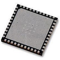
AT89LP52-20MU Atmel, AT89LP52-20MU Datasheet - Page 48

AT89LP52-20MU
Manufacturer Part Number
AT89LP52-20MU
Description
IC MCU 8051 8K FLASH SPI 44VQFN
Manufacturer
Atmel
Series
89LPr
Datasheet
1.AT89LP52-20MU.pdf
(113 pages)
Specifications of AT89LP52-20MU
Core Processor
8051
Core Size
8-Bit
Speed
20MHz
Connectivity
EBI/EMI, I²C, SPI, UART/USART
Peripherals
Brown-out Detect/Reset, POR, PWM, WDT
Number Of I /o
36
Program Memory Size
8KB (8K x 8)
Program Memory Type
FLASH
Ram Size
256 x 8
Voltage - Supply (vcc/vdd)
2.4 V ~ 5.5 V
Oscillator Type
Internal
Operating Temperature
-40°C ~ 85°C
Package / Case
44-VFQFN Exposed Pad
Processor Series
AT89x
Core
8051
Data Bus Width
8 bit
Data Ram Size
256 B
Interface Type
Serial
Maximum Clock Frequency
20 MHz
Number Of Programmable I/os
36
Number Of Timers
3
Operating Supply Voltage
2.7 V to 5.5 V
Maximum Operating Temperature
+ 85 C
Mounting Style
SMD/SMT
Lead Free Status / RoHS Status
Lead free / RoHS Compliant
Eeprom Size
-
Data Converters
-
Lead Free Status / Rohs Status
Details
Available stocks
Company
Part Number
Manufacturer
Quantity
Price
Company:
Part Number:
AT89LP52-20MU
Manufacturer:
Atmel
Quantity:
490
.
Table 11-2.
Table 11-3.
11.5
48
Symbol
TF1
TR1
TF0
TR0
IE1
IT1
IE0
IT0
Symbol
T1OE
T0OE
SPEN
TCON = 88H
Bit Addressable
Bit
TCONB = 91H
Not Bit Addressable
Bit
Clock Output (Pin Toggle Mode)
AT89LP51/52 - Preliminary
Function
Timer 1 overflow flag. Set by hardware on Timer/Counter overflow. Cleared by hardware when the processor vectors
to interrupt routine.
Timer 1 run control bit. Set/cleared by software to turn Timer/Counter on/off.
Timer 0 overflow flag. Set by hardware on Timer/Counter overflow. Cleared by hardware when the processor vectors
to interrupt routine.
Timer 0 run control bit. Set/cleared by software to turn Timer/Counter on/off.
Interrupt 1 edge flag. Set by hardware when external interrupt edge detected. Cleared when interrupt processed.
Interrupt 1 type control bit. Set/cleared by software to specify falling edge/low level triggered external interrupts.
Interrupt 0 edge flag. Set by hardware when external interrupt edge detected. Cleared when interrupt processed.
Interrupt 0 type control bit. Set/cleared by software to specify falling edge/low level triggered external interrupts.
Function
Timer 1 Output Enable. Configures Timer 1 to toggle T1 (P3.5) upon overflow.
Timer 0 Output Enable. Configures Timer 0 to toggle T0 (P3.4) upon overflow.
Enables SPI mode for UART mode 0
TCON
TCONB
T1OE
TF1
7
7
– Timer/Counter Control Register
– Timer/Counter Control Register B
On the AT89LP51/52, Timer 0 and Timer 1 may be independently configured to toggle their
respective counter pins, T0 and T1, on overflow by setting the T0OE or T1OE bits in TCONB.
The C/Tx bits must be set to “0” when in toggle mode and the T0 (P3.4) and T1 (P3.5) pins must
be configured in an output mode. The Timer Overflow Flags and Interrupts will continue to func-
tion while in toggle mode and Timer 1 may still generate the baud rate for the UART. The timer
GATE function also works in toggle mode, allowing the output to be halted by an external input.
Toggle mode can be used with Timer Mode 2 to output a 50% duty cycle clock with 8-bit pro-
grammable frequency. Tx is toggled at every Timer x overflow with the pulse width determined
by the value of THx. An example waveform is given in
the output frequency for Timer 0 in Mode 2.
T0OE
TR1
6
6
SPEN
TF0
Mode 2:
5
5
TR0
4
–
4
f
out
=
System Frequency
------------------------------------------------- -
2
×
IE1
(
3
–
3
256 TH0
–
)
Figure
IT1
2
–
2
×
-------------------- -
TPS
11-5. The following formula gives
1
Reset Value = 0000 0000B
Reset Value = 0000 0000B
+
1
IE0
1
–
1
3709B–MICRO–12/10
IT0
0
–
0


