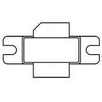
BLF7G27L-100,118 NXP Semiconductors, BLF7G27L-100,118 Datasheet - Page 2

BLF7G27L-100,118
Manufacturer Part Number
BLF7G27L-100,118
Description
TRANSISTOR PWR LDMOS SOT502
Manufacturer
NXP Semiconductors
Datasheet
1.BLF7G27L-100118.pdf
(14 pages)
Specifications of BLF7G27L-100,118
Package / Case
SOT502A
Transistor Type
LDMOS
Frequency
2.6GHz ~ 2.7GHz
Gain
17.5dB
Voltage - Rated
65V
Current - Test
900mA
Voltage - Test
28V
Mounting Style
SMD/SMT
Transistor Polarity
N-Channel
Configuration
Single
Drain-source Breakdown Voltage
65 V
Lead Free Status / RoHS Status
Lead free / RoHS Compliant
Current Rating
-
Power - Output
-
Noise Figure
-
Lead Free Status / Rohs Status
Compliant
NXP Semiconductors
2. Pinning information
3. Ordering information
4. Limiting values
5. Thermal characteristics
BLF7G27L-100_7G27LS-100
Preliminary data sheet
Table 2.
[1]
Table 3.
Table 4.
In accordance with the Absolute Maximum Rating System (IEC 60134).
Table 5.
Pin
BLF7G27L-100 (SOT502A)
1
2
3
BLF7G27LS-100 (SOT502B)
1
2
3
Type number
BLF7G27L-100
BLF7G27LS-100
Symbol
V
V
I
T
Symbol Parameter
R
T
D
stg
j
DS
GS
th(j-c)
Connected to flange.
thermal resistance from junction to case
Pinning
Ordering information
Limiting values
Thermal characteristics
Parameter
drain-source voltage
gate-source voltage
drain current
storage temperature
junction temperature
drain
gate
source
drain
gate
source
Description
All information provided in this document is subject to legal disclaimers.
Package
Name Description
-
-
BLF7G27L-100; BLF7G27LS-100
Rev. 2 — 5 April 2011
flanged LDMOST ceramic package; 2 mounting holes;
2 leads
earless flanged LDMOST ceramic package; 2 leads
Conditions
[1]
[1]
Simplified outline
Conditions
T
case
= 80 °C; P
1
2
1
2
3
Power LDMOS transistor
L
3
= 100 W
Graphic symbol
-
Min
-
−0.5
-
−65
© NXP B.V. 2011. All rights reserved.
2
2
Max
65
+13
28
+150
200
Typ
0.25
sym112
sym112
Version
SOT502A
SOT502B
1
3
1
3
2 of 14
Unit
K/W
Unit
V
V
A
°C
°C


