SS-10GL13T Omron, SS-10GL13T Datasheet - Page 5
SS-10GL13T
Manufacturer Part Number
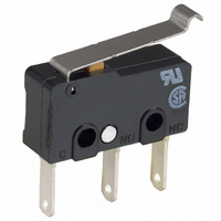
SS-10GL13T
Description
SWITCH 10A LEVER .110QC 50GF
Manufacturer
Omron
Series
SSr
Type
Basic Switchesr
Specifications of SS-10GL13T
Circuit
SPDT
Switch Function
On-Mom
Contact Rating @ Voltage
10.1A @ 125VAC
Actuator Type
Lever, Simulated Roller
Mounting Type
Chassis Mount
Termination Style
Quick Connect - .110" (2.8mm)
Operating Force
50gf
Contact Form
SPDT
Contact Rating
10.1 Amps
Actuator
Simulated Roller Lever
Post Position
Straight Vertical
Microswitch Type
Subminiature
Actuator Style
Simulated Roller Lever
Operating Force Max
50gf
Contact Voltage Ac Nom
250V
Contact Current Max
10A
Switch Terminals
Quick Connect
Body Style
Subminiature
Current, Rating
10 A
Dielectric Strength
600 VAC
Mounting Hole Size
2.4 mm
Number Of Poles
1
Operation
Snap Action
Termination
Quick Connect
Voltage, Rating
125/250 VAC
Pole Throw Configuration
SPDT
Switch Function Configuration
N.O./N.C.
Current Rating (max)
10.1A
Ac Voltage Rating (max)
250VVAC
Dc Voltage Rating (max)
14VVDC
Contact Material
Silver Alloy
Mechanical Life
10000000
Terminal Type
Quick Connect
Product Height (mm)
26.1mm
Product Depth (mm)
6.4mm
Product Length (mm)
22.2mm
Operating Temp Range
-25C to 85C
Lead Free Status / RoHS Status
Lead free / RoHS Compliant
Lead Free Status / RoHS Status
Lead free / RoHS Compliant, Lead free / RoHS Compliant
Other names
SS10GL13T
SW247
SW247


Dimensions
■ Terminals
Note: 1. Unless otherwise specified, all units are in millimeters and a tolerance of ±0.4 mm applies to all dimensions
■ Dimensions and Operating Characteristics
Note: 1. Unless otherwise specified, all units are in millimeters and a tolerance of ±0.4 mm applies to all dimensions
Pin Plunger Models
SS-01(-E, -F)
SS-5(-F)
SS-10
Characteristics
OF max.
RF min.
PT max.
OT min.
MD max.
OP
COM
terminal
COM
terminal
(C)
Solder Terminals
PCB, Left-angled terminal
2. Terminal plate thickness is 0.5 mm for all models.
1.6
2. The following illustrations and dimensions are for solder terminal models.
3. The operating characteristics are for operation in the A direction( )
2.9
Refer to “Terminals” for models with quick-connect terminals (#110) or PCB terminals.
9.5±0.1
8.8
19.8
NO terminal
NO terminal
7.3
NC terminal
SS-01-E
3.2
NC
terminal
0.5 mm
0.5 mm
0.1 mm
25 g
2 g
6.4
6.4
OP
2.9
PT
Three,
1.6-dia. holes
6.4
2.5±0.07 dia.
2.5
2.35
COM terminal (C)
1.6
+0.075
–0.05
Note: Terminal plate thickness is 0.5 mm for all models.
COM
terminal
SS-01-F, SS-5-F
Quick-connect Terminals (#110)
5.1
2
PCB, Right-angled terminal
0.5 mm
0.1 mm
0.5 m
1.6
9.5±0.1
8.8
50 g
2.9
19.8
4 g
7.5
A
7.3
Part number
8.4 ± 0.5 mm
8.8
9.5±0.1
19.8
2.35
NO terminal
9.5
NO terminal
+0.075
–0.05
7.3
10.2
dia. holes
NC terminal
SS-01, SS-5
NC terminal
0.5 mm
0.5 mm
0.1 mm
150 g
25 g
3.2
3.2
6.4
3.2
Three, 1.2 dia.
7.1
2.8
10.6
Three, 1.6 dia.
6.4
Snap Action Switch
COM
terminal
(C)
Left-angled terminal
1.6
PCB Terminals
2.9
0.12 mm
Note: Angled terminal directions
0.6 mm
0.4 mm
SS-10
150 g
25 g
8.8
9.5±0.1
are shown below.
19.8
NO terminal
7.3
Right-angled terminal
3.3
0.5
SS
NC terminal
3.2
0.6
t = 0.5
1.2
99
7.0
Related parts for SS-10GL13T
Image
Part Number
Description
Manufacturer
Datasheet
Request
R

Part Number:
Description:
SWITCH SPDT 10.1A HINGE RLLR SLD
Manufacturer:
Omron
Datasheet:

Part Number:
Description:
SUBMINIATURE BASIC SWITCH
Manufacturer:
Omron
Datasheet:
Part Number:
Description:
SUBMINIATURE BASIC SWITCH
Manufacturer:
Omron
Datasheet:


Part Number:
Description:
FUSE 1A T-LAG IEC AMMO
Manufacturer:
Cooper/Bussmann
Datasheet:

Part Number:
Description:
SWITCH 5A BASIC PC MNT 150GF
Manufacturer:
Omron
Datasheet:

Part Number:
Description:
SWITCH BASIC SPDT .1A 150GF SLD
Manufacturer:
Omron
Datasheet:

Part Number:
Description:
SWITCH SPDT .1A SIM ROLLER SLD
Manufacturer:
Omron
Datasheet:

Part Number:
Description:
SWITCH SPDT 5A PIN PLUNGER SLD
Manufacturer:
Omron
Datasheet:

Part Number:
Description:
SWITCH SPDT 5A SIM ROLLER SLD
Manufacturer:
Omron
Datasheet:

Part Number:
Description:
SW BASIC SPDT 10.1A 150GF SLD
Manufacturer:
Omron
Datasheet:

Part Number:
Description:
SWITCH LEVER SPDT .1A
Manufacturer:
Omron
Datasheet:

Part Number:
Description:
SWITCH LEVER SPDT 5A
Manufacturer:
Omron
Datasheet:

Part Number:
Description:
SWITCH SIM ROLLER SPDT 5A
Manufacturer:
Omron
Datasheet:

Part Number:
Description:
PIN PLUNGER SPDT 1.8OZ/.1AMP
Manufacturer:
Omron
Datasheet: