SS-10 Omron, SS-10 Datasheet
SS-10
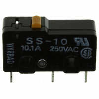
Specifications of SS-10
SS10
SW1060
Available stocks


Related parts for SS-10


SS-10 Summary of contents
Page 1
... SS-01GL2 SS-01GL2T SS-5-FD2 SS-5-F SS-5-FT SS-5D2 SS-5 SS-5T SS-5GL-FD2 SS-5GL-F SS-5GL-FT SS-5GLD2 SS-5GL SS-5GLT SS-5GL13-F SS-5GL13-FT SS-5GL13D2 SS-5GL13 SS-5GL13T SS-5GL2-FD2 SS-5GL2-F SS-5GL2-FT SS-5GL2D2 SS-5GL2 SS-5GL2T — SS-10 SS-10T — SS-10GL SS-10GLT — SS-10GL13 SS-10GL13T — SS-10GL2 SS-10GL2T SS Snap Action Switch 95 ...
Page 2
... Malfunction: 200 m/s (approx. 20G) max. 30 million operations min operations per minute (SS-01, SS-5) 10 million operations min operations per minute (SS-10) 200,000 operations min operations per minute (SS-01, SS-5) 50,000 operations min operations per minute (SS-10) Terminals None: Solder terminals ...
Page 3
... Note: 1. Data in parentheses apply to the SS-10 models only. 2. The above current ratings are the values of the steady-state current. 3. Inductive load has a power factor of 0.4 min. (AC) and a time constant max. (DC). The inductive load rating of the SS-10 is the same as that of SS-5. 4. Lamp load has an inrush current of 10 times the steady-state current 5 ...
Page 4
... Engineering Data ■ Mechanical Service Life SS-01, SS-5 Models (Pin Plunger Models) Ambient temperature: 20±2°C Ambient humidity: 65±5% Without load 40,000 Operating frequency: 60 operations/min 30,000 20,000 10,000 5,000 0.1 0.2 0.3 0.4 0.5 Overtravel (mm) ■ Mounting Panel Mounting All switches may be panel mounted using M2.3 mounting screws with plane washers or spring washers to securely mount the switch. Tighten the screws to a torque of 0.23 to 0.26 N· ...
Page 5
... PCB Terminals 0.6 2.9 3.3 1.6 0.5 8.8 7.3 1.2 9.5±0.1 COM 3.2 terminal 19 0.5 (C) NO terminal NC terminal Note: Angled terminal directions are shown below. Left-angled terminal Right-angled terminal 6.4 SS-10 150 0.6 mm 0 Snap Action Switch 7.0 99 ...
Page 6
... FP OP +0.075 –0.05 10.2 9.5 +0.075 2.35 dia. holes 3.2 –0.05 1.6 6.4 8.8 7.3 5.1 9.5±0.1 Note: Stainless-steel spring lever 19.8 SS-10GL13-F, SS-5GL13-F SS-01GL13, SS-5GL13 1.2 mm 1.2 mm 0.8 mm 0.8 mm 15.5 mm 10.7±0 0.3 (see note dia. 9.5 10 ...
Page 7
... Therefore, manu- general-load ally solder the PCB terminal. models SS-5, SS-10 Wire the quick-connect terminals (#110) with receptacles. Insert the terminals straight into the receptacles. Do not impose excessive force on the terminal in the horizontal direction, otherwise the termi- nal may be deformed or the housing may be damaged ...
Page 8
... To convert millimeters into inches, multiply by 0.03937. To convert grams into ounces, multiply by 0.03527. OMRON ELECTRONIC COMPONENTS LLC 55 E. Commerce Drive, Suite B Schaumburg, IL 60173 847-882-2288 11/10 Cat. No. X303-E-1 SS Snap Action Switch OMRON ON-LINE Global - http://www.omron.com USA - http://www.components.omron.com Specifications subject to change without notice Printed in USA ...