A165-TRM-1 Omron, A165-TRM-1 Datasheet - Page 27
A165-TRM-1
Manufacturer Part Number
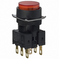
A165-TRM-1
Description
SWITCH PB ROUND MOM SPDT RED
Manufacturer
Omron
Series
A16r
Type
Standardr
Datasheet
1.A16-5DSG.pdf
(28 pages)
Specifications of A165-TRM-1
Circuit
SPDT
Switch Function
On-Mom
Contact Rating @ Voltage
5A @ 125VAC
Actuator Type
Round Button
Mounting Type
Panel Mount
Termination Style
Solder, Quick Connect - .110" (2.8mm)
Contact Form
SPDT
Contact Rating
5 Amps at 125 Volts
Actuator
Round
Mounting Style
Snap In
Illumination
Not Illuminated
Body Shape
Square
Dielectric Strength
2000 Volts
Features
Terminal layout simplifies common wiring
Insulation Resistance
100 MOhms
Mounting Angle
Straight
Operating Force
4.91 N
Water / Moisture Rating
IP65
Lead Free Status / RoHS Status
Lead free / RoHS Compliant
Illumination Type, Color
-
Illumination Voltage (nominal)
-
Lead Free Status / Rohs Status
Lead free / RoHS Compliant
Other names
A165TRM1
Z1326
Z1326


Removing the Lamp
(1) Removing from the Pushbutton End
(2) Removing from the Switch End
Mounting the A16Z Dust Cover
Mounting the A16Z Switch Guard
Set
A16ZJ-5060
The Lamp can be removed by hand once the Switch is removed
using the A16Z-5080 Extractor.
Lamp
Grip the Lamp with the
A16Z-5080 Extractor
and pull to remove.
Cover B
(transparent)
Pushbutton Unit
Cover A
(black)
Switch Unit
Panel
Lock ring
Mounting nut
Switch Guard
Panel
Pushbutton Unit
Lock ring
Mounting nut
Switch Unit
Installing the Lamp
• When mounting the Lamp, make sure it is facing the direction
• The Lamp can be mounted from the Pushbutton end by using the
shown in the following diagram. Insert the Lamp while matching the
protruding part of the Lamp and the small guides on the outer
surface of the Case.
A16Z-5080 Extractor.
The lamp can be mounted by following the opposite procedure for
removing the Lamp.
1. Separate the Dust Cover into 2 parts: cover A and cover B.
2. Insert the Case (Pushbutton Unit) into cover A.
3. Mount these parts together onto the panel.
4. From the back of the panel, mount the lock ring and secure with the
5. Insert cover B into cover A. Ensure that the entire perimeter of cover B
6. Mount the Switch Unit to the Case.
Note: Recommended panel thickness: 0.5 to 2 mm.
1. Insert the Case (Pushbutton Unit) into the Switch Guard.
2. Mount these parts together onto the panel.
3. From the back of the panel, mount the lock ring and secure with the
4. Attach the Switch Unit to the Case.
Note: Recommended panel thickness: 0.5 to 2 mm.
mounting nut.
is securely attached to cover A by pressing in different directions.
mounting nut.
Protruding part
A16
27
Related parts for A165-TRM-1
Image
Part Number
Description
Manufacturer
Datasheet
Request
R

Part Number:
Description:
SWITCH PB ROUND MOM SPDT BLACK
Manufacturer:
Omron
Datasheet:

Part Number:
Description:
SWITCH PB ROUND MOM SPDT WHITE
Manufacturer:
Omron
Datasheet:

Part Number:
Description:
SWITCH PB RECT MOM DPDT WHITE
Manufacturer:
Omron
Datasheet:

Part Number:
Description:
SWITCH PB RECT MOM DPDT YELLOW
Manufacturer:
Omron
Datasheet:

Part Number:
Description:
SWITCH PB ROUND MOM SPDT GREEN
Manufacturer:
Omron
Datasheet:

Part Number:
Description:
SWITCH PB ROUND MOM SPDT YELLOW
Manufacturer:
Omron
Datasheet:

Part Number:
Description:
SWITCH PB ROUND MOM SPDT BLUE
Manufacturer:
Omron
Datasheet:

Part Number:
Description:
SWITCH PB RECT MOM DPDT BLACK
Manufacturer:
Omron
Datasheet:

Part Number:
Description:
SWITCH PB RECT MOM DPDT RED
Manufacturer:
Omron
Datasheet:

Part Number:
Description:
SWITCH PB SQUARE MOM DPDT GREEN
Manufacturer:
Omron
Datasheet:

Part Number:
Description:
SWITCH PB SQUARE MOM DPDT YELLOW
Manufacturer:
Omron
Datasheet:

Part Number:
Description:
SWITCH PB SQUARE MOM DPDT BLUE
Manufacturer:
Omron
Datasheet:

Part Number:
Description:
SWITCH PB RECT MOM DPDT GREEN
Manufacturer:
Omron
Datasheet:

Part Number:
Description:
SWITCH PB SQUARE MOM DPDT BLACK
Manufacturer:
Omron
Datasheet:

Part Number:
Description:
SWITCH PB SQUARE MOM DPDT WHITE
Manufacturer:
Omron
Datasheet: