A22-24AY Omron, A22-24AY Datasheet - Page 47
A22-24AY
Manufacturer Part Number
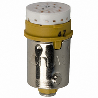
A22-24AY
Description
LAMP A22 SERIES 24VAC/DC LED YLW
Manufacturer
Omron
Type
LED, 10.6 mm Diameterr
Series
A22r
Specifications of A22-24AY
Accessory Type
LED Lamp Replacement
Color
Yellow
Illumination
Illuminated
Contact Rating
8 mAmps at 24 VoltsAC/DC
Height
20 mm
Illumination Color
Yellow
Mounting Style
Snap In
Termination Style
Socket
For Use With/related Products
A22 Series
For Use With
Z1496 - SWITCH PB RND MOM SPST-NO ILLZ1495 - SWITCH PB ILL RND MOM SPST-NOZ1492 - SWITCH PB RND MOM SPST-NC ILLZ1494 - SWITCH PB ILL RND MOM SPST-NOZ1486 - SWITCH PB ILL RND MOM SPST-NOZ1485 - SWITCH PB ILL RND MOM SPST-NOZ1482 - SWITCH PB RND MOM SPST-NC ILLZ1484 - SWITCH PB ILL RND MOM SPST-NOZ1483 - SWITCH PB RND MOM SPST-NO ILLZ1477 - SWITCH PB SQ MOM SPST-NO ILL-YLWZ1476 - SWITCH PB SQ MOM SPST-NO ILL-WHTZ1475 - SWITCH PB SQ MOM SPST-NO ILL-GRNZ1474 - SWITCH PB SQ MOM SPST-NO ILL-BLU
Lead Free Status / RoHS Status
Lead free / RoHS Compliant
Lead Free Status / RoHS Status
Lead free / RoHS Compliant, Lead free / RoHS Compliant
Other names
A2224AY
Z1578
Z1578


A3C
Mounting the Insulation Cover
After securing the Switch to the panel using the mounting nut, pass
the lead wires through the holes in the Insulation Cover and then
perform wiring. Hold the Insulation Cover so that the cylindrical hole
is facing the Switch, and insert the lead wires from the end with the
barriers.
After wiring is completed, mount the Insulation Cover by pushing it
into the Switch.
Mounting the Dust Cover
Mounting the Switch Guard
1. The Dust Cover separates into 2 parts: the cap and the
2. Insert the Switch into the mounting frame. (Align the lock
3. Insert the Switch in the state described in step 2 into the
4. Mount the mounting nut from the back of the panel and tighten
5. Insert the cap into the mounting frame. Ensure that the entire
1. Insert the Switch into the Switch Guard.
2. Insert the Switch into the panel in the state described in step
3. Mount the mounting nut from the back of the panel and tighten
mounting frame.
projection with the recess on the mounting frame.)
panel. (Align the lock protrusion on the mounting frame with
the hole in the panel.)
it.
perimeter of the cap is properly inserted into the mounting
frame by pressing down on the cap from different directions.
1.
it.
Cap (transparent)
Insulation Cover attached to Switch
Switch Lock protrusions
Guard (transparent)
Holder (black)
Mounting frame
Switch terminal
Mounting nut
Panel
Panel
Mounting nut
A3C
45
Related parts for A22-24AY
Image
Part Number
Description
Manufacturer
Datasheet
Request
R

Part Number:
Description:
SWITCH PB ILLUM RND MOM SPST BLU
Manufacturer:
Omron
Datasheet:
Part Number:
Description:
SWITCH PB ILLUM RND MOM SPST BLU
Manufacturer:
Omron
Datasheet:
Part Number:
Description:
SWITCH PB ILLUM RND MOM SPST GRN
Manufacturer:
Omron
Datasheet:
Part Number:
Description:
SWITCH PB ILLUM RND MOM SPST GRN
Manufacturer:
Omron
Datasheet:
Part Number:
Description:
SWITCH PB ILLUM RND MOM SPST RED
Manufacturer:
Omron
Datasheet:
Part Number:
Description:
SWITCH PB ILLUM RND MOM SPST RED
Manufacturer:
Omron
Datasheet:
Part Number:
Description:
SWITCH PB ILLUM RND MOM SPST WHT
Manufacturer:
Omron
Datasheet:
Part Number:
Description:
SWITCH PB ILLUM RND MOM SPST WHT
Manufacturer:
Omron
Datasheet:
Part Number:
Description:
SWITCH PB ILLUM RND MOM SPST YEL
Manufacturer:
Omron
Datasheet:
Part Number:
Description:
SWITCH PB ILLUM RND MOM SPST YEL
Manufacturer:
Omron
Datasheet:
Part Number:
Description:
SWITCH PB ILLUM RND MOM DPST BLU
Manufacturer:
Omron
Datasheet:
Part Number:
Description:
SWITCH PB ILLUM RND MOM SPST BLU
Manufacturer:
Omron
Datasheet:
Part Number:
Description:
SWITCH PB ILLUM RND MOM DPST BLU
Manufacturer:
Omron
Datasheet:
Part Number:
Description:
SWITCH PB ILLUM RND MOM DPST GRN
Manufacturer:
Omron
Datasheet:
Part Number:
Description:
SWITCH PB ILLUM RND MOM SPST GRN
Manufacturer:
Omron
Datasheet: