A22-24AY Omron, A22-24AY Datasheet - Page 263
A22-24AY
Manufacturer Part Number
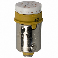
A22-24AY
Description
LAMP A22 SERIES 24VAC/DC LED YLW
Manufacturer
Omron
Type
LED, 10.6 mm Diameterr
Series
A22r
Specifications of A22-24AY
Accessory Type
LED Lamp Replacement
Color
Yellow
Illumination
Illuminated
Contact Rating
8 mAmps at 24 VoltsAC/DC
Height
20 mm
Illumination Color
Yellow
Mounting Style
Snap In
Termination Style
Socket
For Use With/related Products
A22 Series
For Use With
Z1496 - SWITCH PB RND MOM SPST-NO ILLZ1495 - SWITCH PB ILL RND MOM SPST-NOZ1492 - SWITCH PB RND MOM SPST-NC ILLZ1494 - SWITCH PB ILL RND MOM SPST-NOZ1486 - SWITCH PB ILL RND MOM SPST-NOZ1485 - SWITCH PB ILL RND MOM SPST-NOZ1482 - SWITCH PB RND MOM SPST-NC ILLZ1484 - SWITCH PB ILL RND MOM SPST-NOZ1483 - SWITCH PB RND MOM SPST-NO ILLZ1477 - SWITCH PB SQ MOM SPST-NO ILL-YLWZ1476 - SWITCH PB SQ MOM SPST-NO ILL-WHTZ1475 - SWITCH PB SQ MOM SPST-NO ILL-GRNZ1474 - SWITCH PB SQ MOM SPST-NO ILL-BLU
Lead Free Status / RoHS Status
Lead free / RoHS Compliant
Lead Free Status / RoHS Status
Lead free / RoHS Compliant, Lead free / RoHS Compliant
Other names
A2224AY
Z1578
Z1578


M2P
(If using a Switch Guard or Seal Cover, refer to the panel cutout diagrams.)
M2PJ (Rectangular) Models
Note: 1. n: Number of Units
M2PA (Square) Models
Note: 1. n: Number of Units
Flange
mount
models
Barrier
mount
models
Flange mount
models
Barrier mount
models
Panel Cutout
Classification
2. Recommended panel thickness: 1 to 5 mm
3. Mount the panel before mounting the Switch Guard.
4. If the panel is to be finished (e.g., coated), make sure that the panel meets the specified dimensions after the coating.
2. Recommended panel thickness: 1 to 5 mm
3. If the panel is to be finished (e.g., coated), make sure that the panel meets the specified dimensions after the coating.
Individual
mounting
(Horizontal)
Multiple
mounting
(Horizontal)
Individual
mounting
(Vertical)
Multiple
mounting
(Vertical)
Individual
mounting
(Horizontal)
Multiple
mounting
(Horizontal)
Individual
mounting
(Vertical)
Multiple
mounting
(Vertical)
Classification
Individual
mounting
Multiple mounting
Individual
mounting
Multiple mounting
25±0.1
25±0.1
32±0.1
32±0.1
34
27
34
27
32±0.1
25±0.1
32±0.1
1
39
1
1
1
Mounting design
25n±0.5
2
26n+6±1
2
25±0.1
2
25±0.1
32n±0.5
2
33n+6±1
Mount to long mounting
plate (A3PJ-3002) be-
fore use.
27
27
Mounting design
25±0.1
1
1
n
32
n
Mount to long
mounting plate
(A3PJ-3002)
before use.
25n±0.1
n
2
26n+6.5±1
2
Mount to long
mounting plate
(A3PJ-3002)
before use.
Mount to long
mounting plate
(A3PJ-3002)
before use.
n
n
n
30.5±0.3
30.5±0.3
23.5±0.3
30.5±0.3
23.5±0.3
23.5±0.3
23.5±0.3
30.5±0.3
23.5±0.3
23.5±0.3
23.5±0.3
23.5±0.3
23.5±0.3
30.5±0.3
36.4±0.3
29.4±0.3
25n–1.5±0.3
Panel cutout
25.9n+3.5±0.3
27.8±0.3
32n–1.5±0.3
32.9n+3.5±0.3
Panel cutout
22.5±0.3
25n–2.5±0.3
26n+2.5±0.3
Panel cutout spacing between rows
of Units:
Panel cutout spacing between rows
of Units:
(Dotted line indicates the position of
each mounting barrier.)
Panel cutout spacing between rows
of Units:
For barrier mount models, refer to
Accessories on page 234.
Panel cutout spacing between rows
of Units:
of Units:
(Dotted line indicates the position
of each mounting barrier.)
6 min.
6 min.
6 min.
6 min.
Remarks
Remarks
3 min.
3 min.
6 min.
6 min.
M2P
261
Related parts for A22-24AY
Image
Part Number
Description
Manufacturer
Datasheet
Request
R

Part Number:
Description:
SWITCH PB ILLUM RND MOM SPST BLU
Manufacturer:
Omron
Datasheet:
Part Number:
Description:
SWITCH PB ILLUM RND MOM SPST BLU
Manufacturer:
Omron
Datasheet:
Part Number:
Description:
SWITCH PB ILLUM RND MOM SPST GRN
Manufacturer:
Omron
Datasheet:
Part Number:
Description:
SWITCH PB ILLUM RND MOM SPST GRN
Manufacturer:
Omron
Datasheet:
Part Number:
Description:
SWITCH PB ILLUM RND MOM SPST RED
Manufacturer:
Omron
Datasheet:
Part Number:
Description:
SWITCH PB ILLUM RND MOM SPST RED
Manufacturer:
Omron
Datasheet:
Part Number:
Description:
SWITCH PB ILLUM RND MOM SPST WHT
Manufacturer:
Omron
Datasheet:
Part Number:
Description:
SWITCH PB ILLUM RND MOM SPST WHT
Manufacturer:
Omron
Datasheet:
Part Number:
Description:
SWITCH PB ILLUM RND MOM SPST YEL
Manufacturer:
Omron
Datasheet:
Part Number:
Description:
SWITCH PB ILLUM RND MOM SPST YEL
Manufacturer:
Omron
Datasheet:
Part Number:
Description:
SWITCH PB ILLUM RND MOM DPST BLU
Manufacturer:
Omron
Datasheet:
Part Number:
Description:
SWITCH PB ILLUM RND MOM SPST BLU
Manufacturer:
Omron
Datasheet:
Part Number:
Description:
SWITCH PB ILLUM RND MOM DPST BLU
Manufacturer:
Omron
Datasheet:
Part Number:
Description:
SWITCH PB ILLUM RND MOM DPST GRN
Manufacturer:
Omron
Datasheet:
Part Number:
Description:
SWITCH PB ILLUM RND MOM SPST GRN
Manufacturer:
Omron
Datasheet: