A22-24AY Omron, A22-24AY Datasheet - Page 200
A22-24AY
Manufacturer Part Number
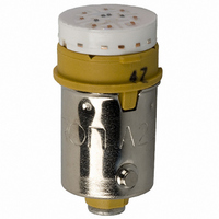
A22-24AY
Description
LAMP A22 SERIES 24VAC/DC LED YLW
Manufacturer
Omron
Type
LED, 10.6 mm Diameterr
Series
A22r
Specifications of A22-24AY
Accessory Type
LED Lamp Replacement
Color
Yellow
Illumination
Illuminated
Contact Rating
8 mAmps at 24 VoltsAC/DC
Height
20 mm
Illumination Color
Yellow
Mounting Style
Snap In
Termination Style
Socket
For Use With/related Products
A22 Series
For Use With
Z1496 - SWITCH PB RND MOM SPST-NO ILLZ1495 - SWITCH PB ILL RND MOM SPST-NOZ1492 - SWITCH PB RND MOM SPST-NC ILLZ1494 - SWITCH PB ILL RND MOM SPST-NOZ1486 - SWITCH PB ILL RND MOM SPST-NOZ1485 - SWITCH PB ILL RND MOM SPST-NOZ1482 - SWITCH PB RND MOM SPST-NC ILLZ1484 - SWITCH PB ILL RND MOM SPST-NOZ1483 - SWITCH PB RND MOM SPST-NO ILLZ1477 - SWITCH PB SQ MOM SPST-NO ILL-YLWZ1476 - SWITCH PB SQ MOM SPST-NO ILL-WHTZ1475 - SWITCH PB SQ MOM SPST-NO ILL-GRNZ1474 - SWITCH PB SQ MOM SPST-NO ILL-BLU
Lead Free Status / RoHS Status
Lead free / RoHS Compliant
Lead Free Status / RoHS Status
Lead free / RoHS Compliant, Lead free / RoHS Compliant
Other names
A2224AY
Z1578
Z1578


1. When the panel cutout dimension is 25 dia., remove the supplied
2. When the panel cutout dimension is 30 dia., the A22Z-A30
Matrix Mounting
1. The following diagram provides the dimensions for mounting indi-
198
rubber washer and mount the 25-dia. Ring as shown below.
(Since the A22Z-R25 is not attached to the main body, order sep-
arately.)
Attachment is not attached to the main body, order separately.
vidual Switches, Legend Plates, and Lock Rings with leads con-
nected directly to Switch terminals.
Hold here
Lock Ring
Panel
Mounting nut
Rubber washer
Panel
Lock Ring
22.3 dia.
22.3 dia.
22 dia.
25 dia.
25 dia.
30
Mounting nut
25-dia. Ring
Rubber washer
(mounted to Operation Unit)
30-dia. Resin Attachment
(A22Z-A30)
Operation Unit
Operation Unit
Rubber washer (included)
Mounting Ring
Lock Ring
Mounting panel
(A22Z-R25)
A
Pro-
jecting
part
Panel
Lock Ring
2. The following diagram provides the dimensions for mounting
Dimensions A and B between mounting hole centers are given in the
following tables.
For 1., Above
For 2., Above
Note: 1. The above dimensions are the minimum dimensions when
Mounting the Switch on the Operation
Unit
Insert the Operation Unit into the Switch Unit, aligning the arrow
mark inscribed on the Case with the lever on the Switch Blocks, then
move the lever in the direction indicated by the arrow in the following
figure.
Removing the Switch
A22-10, A22-10S, A22-01, A22-01S
A22-20, A22-20S, A-22-02, A22-02S, A22-11, A22-11S
Naked crimp ter-
minals
Crimp terminals
with insulating
sheaths
Type of crimp
Large Legend Plates with crimp terminals connected to Switch
terminals.
terminal
2. When using pushbuttons exceeding 30 mm, adjust dimen-
using the applicable wiring materials listed on page 201. If
any other materials are used, check the suitability of dimen-
sions in advance.
sion A or B accordingly. (When mounting the A22-M@ in a
matrix, “30 mm” would have to be increased to 40 mm.
A22-10, A22-10S, A22-01, A22-01S 51 mm min.
A22-20, A22-20S, A22-02, A22-02S,
A22-11, A22-11S
A22-10, A22-10S, A22-01, A22-01S 60 mm min.
A22-20, A22-20S, A22-02, A22-02S,
A22-11, A22-11S
Switch model
Switch model
30
Operation Unit
B
Arrow mark
61 mm min.
70 mm min.
45 mm min.
55 mm min.
Dimension B
Dimension A
Lever
Related parts for A22-24AY
Image
Part Number
Description
Manufacturer
Datasheet
Request
R

Part Number:
Description:
SWITCH PB ILLUM RND MOM SPST BLU
Manufacturer:
Omron
Datasheet:
Part Number:
Description:
SWITCH PB ILLUM RND MOM SPST BLU
Manufacturer:
Omron
Datasheet:
Part Number:
Description:
SWITCH PB ILLUM RND MOM SPST GRN
Manufacturer:
Omron
Datasheet:
Part Number:
Description:
SWITCH PB ILLUM RND MOM SPST GRN
Manufacturer:
Omron
Datasheet:
Part Number:
Description:
SWITCH PB ILLUM RND MOM SPST RED
Manufacturer:
Omron
Datasheet:
Part Number:
Description:
SWITCH PB ILLUM RND MOM SPST RED
Manufacturer:
Omron
Datasheet:
Part Number:
Description:
SWITCH PB ILLUM RND MOM SPST WHT
Manufacturer:
Omron
Datasheet:
Part Number:
Description:
SWITCH PB ILLUM RND MOM SPST WHT
Manufacturer:
Omron
Datasheet:
Part Number:
Description:
SWITCH PB ILLUM RND MOM SPST YEL
Manufacturer:
Omron
Datasheet:
Part Number:
Description:
SWITCH PB ILLUM RND MOM SPST YEL
Manufacturer:
Omron
Datasheet:
Part Number:
Description:
SWITCH PB ILLUM RND MOM DPST BLU
Manufacturer:
Omron
Datasheet:
Part Number:
Description:
SWITCH PB ILLUM RND MOM SPST BLU
Manufacturer:
Omron
Datasheet:
Part Number:
Description:
SWITCH PB ILLUM RND MOM DPST BLU
Manufacturer:
Omron
Datasheet:
Part Number:
Description:
SWITCH PB ILLUM RND MOM DPST GRN
Manufacturer:
Omron
Datasheet:
Part Number:
Description:
SWITCH PB ILLUM RND MOM SPST GRN
Manufacturer:
Omron
Datasheet: