GA200SA60U Vishay, GA200SA60U Datasheet - Page 2
GA200SA60U
Manufacturer Part Number
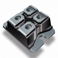
GA200SA60U
Description
IGBT UFAST 600V 100A SOT227
Manufacturer
Vishay
Specifications of GA200SA60U
Configuration
Single
Voltage - Collector Emitter Breakdown (max)
600V
Vce(on) (max) @ Vge, Ic
1.9V @ 15V, 100A
Current - Collector (ic) (max)
200A
Current - Collector Cutoff (max)
1mA
Input Capacitance (cies) @ Vce
16.5nF @ 30V
Power - Max
500W
Input
Standard
Ntc Thermistor
No
Mounting Type
Chassis Mount
Package / Case
SOT-227, miniBLOC
Lead Free Status / RoHS Status
Contains lead / RoHS non-compliant
Igbt Type
-
Lead Free Status / Rohs Status
Not Compliant
Other names
*GA200SA60U
VS-GA200SA60U
VS-GA200SA60U
VSGA200SA60U
VSGA200SA60U
VS-GA200SA60U
VS-GA200SA60U
VSGA200SA60U
VSGA200SA60U
Available stocks
Company
Part Number
Manufacturer
Quantity
Price
Company:

Part Number:
GA200SA60U
Manufacturer:
IR
Quantity:
1 000
Part Number:
GA200SA60U
Quantity:
62
Part Number:
GA200SA60UP
Quantity:
63
Company:
Part Number:
GA200SA60UPBF
Manufacturer:
AVX
Quantity:
25 000


GA200SA60UP
Vishay High Power Products
www.vishay.com
2
ELECTRICAL SPECIFICATIONS (T
PARAMETER
Collector to emitter breakdown voltage
Emitter to collector breakdown voltage
Temperature coeff. of breakdown voltage ΔV
Collector to emitter saturation voltage
Gate threshold voltage
Temperature coeff. of threshold voltage
Forward transconductance
Zero gate voltage collector current
Gate to emitter leakage current
SWITCHING CHARACTERISTICS (T
PARAMETER
Total gate charge (turn-on)
Gate-emitter charge (turn-on)
Gate-collector charge (turn-on)
Turn-on delay time
Rise time
Turn-off delay time
Fall time
Turn-on switching loss
Turn-off switching loss
Total switching loss
Turn-on delay time
Rise time
Turn-off delay time
Fall time
Total switching loss
Internal emitter inductance
Input capacitance
Output capacitance
Reverse transfer capacitance
For technical questions, contact:
ΔV
SYMBOL
SYMBOL
V
V
(BR)CES
V
V
GE(th)
(BR)CES
(BR)ECS
t
t
t
t
C
C
I
I
C
CE(on)
Q
Q
d(on)
d(off)
E
E
d(on)
d(off)
GE(th)
GES
Q
E
E
g
CES
L
t
t
t
t
oes
res
on
off
ies
ge
gc
fe
r
f
ts
r
f
ts
E
Insulated Gate Bipolar Transistor
g
J
/ΔT
(Ultrafast Speed IGBT), 100 A
/ΔT
= 25 °C unless otherwise specified)
J
= 25 °C unless otherwise specified)
J
J
I
V
V
T
I
V
V
R
Energy losses include “tail”
See fig. 9, 10, 14
T
I
V
Energy losses include “tail”
See fig. 10, 11, 14
Measured 5 mm from package
V
V
ƒ = 1.0 MHz; See fig. 7
V
V
Pulse width ≤ 80 µs; duty factor ≤ 0.1 %
V
I
I
I
V
V
V
Pulse width 5.0 µs, single shot
V
V
V
C
C
C
C
C
C
J
J
CC
GE
CC
GE
GE
GE
CC
GE
GE
GE
CE
CE
CE
GE
GE
GE
G
= 100 A
= 200 A
= 100 A, T
= 100 A
= 100 A
= 100 A, V
= 25 °C
= 150 °C
= 2.0 Ω
= V
= V
= 100 V, I
= 400 V
= 15 V; See fig. 8
= 480 V
= 15 V
= 15 V, R
= 0 V
= 30 V
= 0 V, I
= 0 V, I
= 0 V, I
= 0 V, V
= 0 V, V
= ± 20 V
GE
GE
TEST CONDITIONS
TEST CONDITIONS
, I
, I
C
C
C
C
C
CE
CE
J
CC
indmodules@vishay.com
= 250 µA
= 1.0 A
= 10 mA
G
= 250 µA
= 2.0 mA
C
= 150 °C
= 600 V
= 600 V, T
= 480 V
= 2.0 Ω
= 100 A
J
V
See fig. 2, 5
= 150 °C
GE
= 15 V
MIN.
MIN.
600
3.0
18
79
-
-
-
-
-
-
-
-
-
-
-
-
-
-
-
-
-
-
-
-
-
-
-
-
-
-
-
16 500
TYP.
TYP.
1000
0.38
1.60
1.92
1.54
0.98
3.48
4.46
7.24
- 11
770
100
260
130
300
160
460
200
5.0
54
79
56
75
Document Number: 94364
-
-
-
-
-
-
-
Revision: 02-Sep-09
MAX.
± 250
MAX.
1200
150
380
200
450
1.9
6.0
1.0
7.6
10
-
-
-
-
-
-
-
-
-
-
-
-
-
-
-
-
-
-
-
-
UNITS
UNITS
mV/°C
V/°C
mA
mJ
mJ
nA
nC
nH
pF
ns
ns
V
V
S
Related parts for GA200SA60U
Image
Part Number
Description
Manufacturer
Datasheet
Request
R

Part Number:
Description:
Power Inductors 223uH Power Inductor
Manufacturer:
Gowanda Electronics
Datasheet:
Part Number:
Description:
Power Inductors 100uH 0.208ohms 1.2A
Manufacturer:
Gowanda Electronics
Datasheet:


Part Number:
Description:
357-036-542-201 CARDEDGE 36POS DL .156 BLK LOPRO
Manufacturer:
Vishay
Datasheet:
Part Number:
Description:
357-036-542-201 CARDEDGE 36POS DL .156 BLK LOPRO
Manufacturer:
Vishay
Datasheet:
Part Number:
Description:
357-036-542-201 CARDEDGE 36POS DL .156 BLK LOPRO
Manufacturer:
Vishay
Datasheet:
Part Number:
Description:
357-036-542-201 CARDEDGE 36POS DL .156 BLK LOPRO
Manufacturer:
Vishay
Datasheet:
Part Number:
Description:
357-036-542-201 CARDEDGE 36POS DL .156 BLK LOPRO
Manufacturer:
Vishay
Datasheet:
Part Number:
Description:
357-036-542-201 CARDEDGE 36POS DL .156 BLK LOPRO
Manufacturer:
Vishay
Datasheet:
Part Number:
Description:
357-036-542-201 CARDEDGE 36POS DL .156 BLK LOPRO
Manufacturer:
Vishay
Datasheet:
Part Number:
Description:
357-036-542-201 CARDEDGE 36POS DL .156 BLK LOPRO
Manufacturer:
Vishay
Datasheet:
Part Number:
Description:
357-036-542-201 CARDEDGE 36POS DL .156 BLK LOPRO
Manufacturer:
Vishay
Datasheet:
Part Number:
Description:
357-036-542-201 CARDEDGE 36POS DL .156 BLK LOPRO
Manufacturer:
Vishay
Datasheet:
Part Number:
Description:
357-036-542-201 CARDEDGE 36POS DL .156 BLK LOPRO
Manufacturer:
Vishay
Datasheet:
Part Number:
Description:
357-036-542-201 CARDEDGE 36POS DL .156 BLK LOPRO
Manufacturer:
Vishay
Datasheet: