APT50GF120JRDQ3 Microsemi Power Products Group, APT50GF120JRDQ3 Datasheet - Page 7
APT50GF120JRDQ3
Manufacturer Part Number
APT50GF120JRDQ3
Description
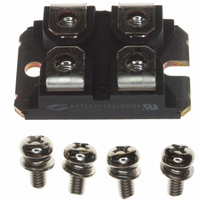
IGBT 1200V 120A 521W SOT227
Manufacturer
Microsemi Power Products Group
Datasheet
1.APT50GF120JRDQ3.pdf
(9 pages)
Specifications of APT50GF120JRDQ3
Igbt Type
NPT
Configuration
Single
Voltage - Collector Emitter Breakdown (max)
1200V
Vce(on) (max) @ Vge, Ic
3V @ 15V, 75A
Current - Collector (ic) (max)
120A
Current - Collector Cutoff (max)
750µA
Input Capacitance (cies) @ Vce
5.32nF @ 25V
Power - Max
521W
Input
Standard
Ntc Thermistor
No
Mounting Type
Chassis Mount
Package / Case
ISOTOP
Lead Free Status / RoHS Status
Lead free / RoHS Compliant
Other names
APT50GF120JRDQ3MI
APT50GF120JRDQ3MI
APT50GF120JRDQ3MI
Available stocks
Company
Part Number
Manufacturer
Quantity
Price
Company:

Part Number:
APT50GF120JRDQ3
Manufacturer:
Microsemi Power Products Group
Quantity:
135
Company:
Part Number:
APT50GF120JRDQ3
Manufacturer:
APT
Quantity:
1 000
Part Number:
APT50GF120JRDQ3
Quantity:
122


TYPICAL PERFORMANCE CURVES
MAXIMUM RATINGS
STATIC ELECTRICAL CHARACTERISTICS
DYNAMIC CHARACTERISTICS
Symbol
I
Symbol
Symbol
F
I
ULTRAFAST SOFT RECOVERY ANTI-PARALLEL DIODE
F
(RMS)
I
I
I
I
RRM
RRM
RRM
FSM
(AV)
Q
Q
Q
V
t
t
t
t
rr
rr
rr
rr
F
rr
rr
rr
0.60
0.50
0.40
0.30
0.20
0.10
Characteristic / Test Conditions
Maximum Average Forward Current (T
RMS Forward Current (Square wave, 50% duty)
Non-Repetitive Forward Surge Current (T
Characteristic
Reverse Recovery Time
Reverse Recovery Time
Reverse Recovery Charge
Maximum Reverse Recovery Current
Reverse Recovery Time
Reverse Recovery Charge
Maximum Reverse Recovery Current
Reverse Recovery Time
Reverse Recovery Charge
Maximum Reverse Recovery Current
Characteristic / Test Conditions
Forward Voltage
0
10
-5
FIGURE 24a. MAXIMUM EFFECTIVE TRANSIENT THERMAL IMPEDANCE, JUNCTION-TO-CASE vs. PULSE DURATION
D = 0.9
0.7
0.5
0.3
0.1
0.05
10
-4
Dissipated Power
FIGURE 24b, TRANSIENT THERMAL IMPEDANCE MODEL
I
F
= 1A, di
(Watts)
RECTANGULAR PULSE DURATION (seconds)
F
/dt = -100A/µs, V
C
SINGLE PULSE
= 85°C, Duty Cycle = 0.5)
10
J
T
-3
J
= 45°C, 8.3ms)
I
I
I
(°C)
I
F
F
F
I
I
F
F
F
= 75A
= 150A
= 75A, T
V
V
= 60A, di
0.006
V
= 60A, di
= 60A, di
R
R
0.149
R
= 800V, T
= 800V, T
Test Conditions
= 800V, T
R
J
0.091
= 125°C
= 30V, T
F
Z
impedances: Case to sink,
sink to ambient, etc. Set to
zero when modeling only
the case to junction.
0.238
F
F
EXT
/dt = -1000A/µs
All Ratings: T
/dt = -200A/µs
/dt = -200A/µs
are the external thermal
C
C
C
10
= 125°C
= 125°C
= 25°C
-2
0.524
0.174
J
= 25°C
T
C
(°C)
C
= 25°C unless otherwise specified.
Note:
MIN
MIN
Peak T J = P DM x Z θJC + T C
APT50GF120JRDQ3
-
-
-
-
-
-
-
-
-
-
Duty Factor D =
10
-1
t 1
2890
4720
3.48
2.17
TYP
TYP
265
560
350
150
540
2.8
t 2
60
13
40
60
73
5
APT50GF120JRDQ3
t 1
/
t 2
MAX-
MAX
-
-
-
1.0
Amps
Amps
UNIT
Amps
Amps
UNIT
Volts
UNIT
nC
nC
nC
ns
ns
ns
Related parts for APT50GF120JRDQ3
Image
Part Number
Description
Manufacturer
Datasheet
Request
R

Part Number:
Description:
IGBT 600V 100A 463W TO247
Manufacturer:
Microsemi Power Products Group
Datasheet:

Part Number:
Description:
IGBT 600V 198A 833W TO264
Manufacturer:
Microsemi Power Products Group
Datasheet:
Part Number:
Description:
IGBT 600V 41A 187W TO247
Manufacturer:
Microsemi Power Products Group
Datasheet:
Part Number:
Description:
MOSFET N-CH 600V 23A TO-247
Manufacturer:
Microsemi Power Products Group
Datasheet:

Part Number:
Description:
MOSFET N-CH 500V 17A TO-220
Manufacturer:
Microsemi Power Products Group
Datasheet:
Part Number:
Description:
MOSFET N-CH 1200V 3.5A TO-220
Manufacturer:
Microsemi Power Products Group
Datasheet:
Part Number:
Description:
MOSFET N-CH 500V 22A TO-247
Manufacturer:
Microsemi Power Products Group
Datasheet:
Part Number:
Description:
MOSFET N-CH 100V 75A TO-247
Manufacturer:
Microsemi Power Products Group
Datasheet:
Part Number:
Description:
MOSFET N-CH 200V 56A TO-247
Manufacturer:
Microsemi Power Products Group
Datasheet:
Part Number:
Description:
MOSFET N-CH 500V 27A TO-247
Manufacturer:
Microsemi Power Products Group
Datasheet:
Part Number:
Description:
MOSFET N-CH 300V 40A TO-247
Manufacturer:
Microsemi Power Products Group
Datasheet:
Part Number:
Description:
MOSFET N-CH 200V 59A TO-247
Manufacturer:
Microsemi Power Products Group
Datasheet:
Part Number:
Description:
MOSFET N-CH 500V 26A TO-247
Manufacturer:
Microsemi Power Products Group
Datasheet:
Part Number:
Description:
MOSFET N-CH 300V 40A TO-247
Manufacturer:
Microsemi Power Products Group
Datasheet:
Part Number:
Description:
MOSFET N-CH 200V 65A TO-247
Manufacturer:
Microsemi Power Products Group
Datasheet: