APT60GT60JR Microsemi Power Products Group, APT60GT60JR Datasheet - Page 3
APT60GT60JR
Manufacturer Part Number
APT60GT60JR
Description
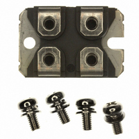
IGBT 600V 93A 378W SOT227
Manufacturer
Microsemi Power Products Group
Series
Thunderbolt IGBT®r
Datasheet
1.APT60GT60JR.pdf
(5 pages)
Specifications of APT60GT60JR
Igbt Type
NPT
Configuration
Single
Voltage - Collector Emitter Breakdown (max)
600V
Vce(on) (max) @ Vge, Ic
2.5V @ 15V, 60A
Current - Collector (ic) (max)
93A
Current - Collector Cutoff (max)
80µA
Input Capacitance (cies) @ Vce
1.6nF @ 25V
Power - Max
378W
Input
Standard
Ntc Thermistor
No
Mounting Type
Chassis Mount
Package / Case
ISOTOP
Lead Free Status / RoHS Status
Lead free / RoHS Compliant
Other names
APT60GT60JRMI
APT60GT60JRMI
APT60GT60JRMI
Available stocks
Company
Part Number
Manufacturer
Quantity
Price
Company:

Part Number:
APT60GT60JR
Manufacturer:
Microsemi Power Products Group
Quantity:
135
Company:
Part Number:
APT60GT60JRD
Manufacturer:
APT
Quantity:
25
Company:
Part Number:
APT60GT60JRD
Manufacturer:
APT
Quantity:
15 500
Company:
Part Number:
APT60GT60JRDQ2
Manufacturer:
NIEC
Quantity:
1 000
Part Number:
APT60GT60JRDQ2
Quantity:
115
Company:
Part Number:
APT60GT60JRDX
Manufacturer:
APT
Quantity:
25


Figure 5, Typical Capacitance vs Collector-To-Emitter Voltage
10,000
0.005
0.001
1,000
0.35
0.05
0.01
Figure 3, Typical Output Characteristics @ V
160
120
160
120
100
0.1
V
Figure 1, Typical Output Characteristics (T
V
V
80
40
80
40
CE
CE
CE
0
0
0.01
10
0
0
, COLLECTOR-TO-EMITTER VOLTAGE (VOLTS)
, COLLECTOR-TO-EMITTER VOLTAGE (VOLTS)
, COLLECTOR-TO-EMITTER VOLTAGE (VOLTS)
250 µsec. Pulse Test
-5
V
GE
D=0.5
4
1
= 15V
f = 1MHz
0.02
0.1
0.05
0.01
T
T
T
0.1
0.2
Figure 7, Maximum Effective Transient Thermal Impedance, Junction-To-Case vs Pulse Duration
C
C
C
=+25°C
=+150°C
=-55°C
V
GE
8
2
=17, 15, 13, 11 & 10V
10
SINGLE PULSE
-4
1.0
12
3
16
10
4
C
C
C
9V
8V
6V
RECTANGULAR PULSE DURATION (SECONDS)
7V
ies
oes
res
J
10
GE
= 25°C)
-3
50
20
5
= 15V
10
-2
160
120
Figure 2, Typical Output Characteristics (T
200
100
Figure 4, Maximum Forward Safe Operating Area
V
V
Figure 6, Gate Charges vs Gate-To-Emitter Voltage
80
40
10
20
16
12
CE
CE
0
5
1
8
4
0
0
1
0
, COLLECTOR-TO-EMITTER VOLTAGE (VOLTS)
, COLLECTOR-TO-EMITTER VOLTAGE (VOLTS)
OPERATION
V CE (SAT)
T
LIMITED
I
J
C
10
BY
= +25°C
T
T
SINGLE PULSE
= I
C
J
-1
Q
=+150°C
C2
=+25°C
g
4
, TOTAL GATE CHARGE (nC)
100
5
V
CE
Note:
10
Peak T J = P DM x Z JC + T C
=300V
8
V
Duty Factor D =
GE
V
200
CE
=17, 15, 13, 11 & 10V
1.0
=120V
t 1
12
50 100
t 2
V
CE
300
t 1
=480V
/ t 2
16
9V
7V
8V
6V
5V
J
= 150°C)
600
400
10
20
100µs
1ms
10ms
Related parts for APT60GT60JR
Image
Part Number
Description
Manufacturer
Datasheet
Request
R

Part Number:
Description:
IGBT 600V 100A 463W TO247
Manufacturer:
Microsemi Power Products Group
Datasheet:

Part Number:
Description:
IGBT 600V 198A 833W TO264
Manufacturer:
Microsemi Power Products Group
Datasheet:
Part Number:
Description:
IGBT 600V 41A 187W TO247
Manufacturer:
Microsemi Power Products Group
Datasheet:
Part Number:
Description:
MOSFET N-CH 600V 23A TO-247
Manufacturer:
Microsemi Power Products Group
Datasheet:

Part Number:
Description:
MOSFET N-CH 500V 17A TO-220
Manufacturer:
Microsemi Power Products Group
Datasheet:
Part Number:
Description:
MOSFET N-CH 1200V 3.5A TO-220
Manufacturer:
Microsemi Power Products Group
Datasheet:
Part Number:
Description:
MOSFET N-CH 500V 22A TO-247
Manufacturer:
Microsemi Power Products Group
Datasheet:
Part Number:
Description:
MOSFET N-CH 100V 75A TO-247
Manufacturer:
Microsemi Power Products Group
Datasheet:
Part Number:
Description:
MOSFET N-CH 200V 56A TO-247
Manufacturer:
Microsemi Power Products Group
Datasheet:
Part Number:
Description:
MOSFET N-CH 500V 27A TO-247
Manufacturer:
Microsemi Power Products Group
Datasheet:
Part Number:
Description:
MOSFET N-CH 300V 40A TO-247
Manufacturer:
Microsemi Power Products Group
Datasheet:
Part Number:
Description:
MOSFET N-CH 200V 59A TO-247
Manufacturer:
Microsemi Power Products Group
Datasheet:
Part Number:
Description:
MOSFET N-CH 500V 26A TO-247
Manufacturer:
Microsemi Power Products Group
Datasheet:
Part Number:
Description:
MOSFET N-CH 300V 40A TO-247
Manufacturer:
Microsemi Power Products Group
Datasheet:
Part Number:
Description:
MOSFET N-CH 200V 65A TO-247
Manufacturer:
Microsemi Power Products Group
Datasheet: