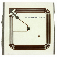
SRI512-A3S/1GE STMicroelectronics, SRI512-A3S/1GE Datasheet - Page 24

SRI512-A3S/1GE
Manufacturer Part Number
SRI512-A3S/1GE
Description
IC MEMORY 13.56MHZ EEPRM ADH ANT
Manufacturer
STMicroelectronics
Series
SRI512r
Specifications of SRI512-A3S/1GE
Rf Type
Read / Write
Frequency
13.56MHz
Features
ISO14443-B
Package / Case
38mm x 38mm
Operating Temperature (max)
85C
Operating Temperature Classification
Commercial
Lead Free Status / RoHS Status
Lead free / RoHS Compliant
Other names
497-5535-2
Anticollision
7
24/47
Anticollision
The SRI512 provides an anticollision mechanism that searches for the Chip_ID of each
device that is present in the reader field range. When known, the Chip_ID is used to select
an SRI512 individually, and access its memory. The anticollision sequence is managed by
the reader through a set of commands described in
●
●
●
The reader is the master of the communication with one or more SRI512 device(s). It
initiates the tag communication activity by issuing an Initiate(), Pcall16() or Slot_marker()
command to prompt the SRI512 to answer. During the anticollision sequence, it might
happen that two or more SRI512 devices respond simultaneously, so causing a collision.
The command set allows the reader to handle the sequence, to separate SRI512
transmissions into different time slots. Once the anticollision sequence has completed,
SRI512 communication is fully under the control of the reader, allowing only one SRI512 to
transmit at a time.
The Anticollision scheme is based on the definition of time slots during which the SRI512
devices are invited to answer with minimum identification data: the Chip_ID. The number of
slots is fixed at 16 for the Pcall16() command. For the Initiate() command, there is no slot
and the SRI512 answers after the command is issued. SRI512 devices are allowed to
answer only once during the anticollision sequence. Consequently, even if there are several
SRI512 devices present in the reader field, there will probably be a slot in which only one
SRI512 answers, allowing the reader to capture its Chip_ID. Using the Chip_ID, the reader
can then establish a communication channel with the identified SRI512. The purpose of the
anticollision sequence is to allow the reader to select one SRI512 at a time.
The SRI512 is given an 8-bit Chip_ID value used by the reader to select only one among up
to 256 tags present within its field range. The Chip_ID is initialized with a random value
during the Ready state, or after an Initiate() command in the Inventory state.
The four least significant bits (b
Chip_slot_number. This 4-bit value is used by the Pcall16() and Slot_marker() commands
during the anticollision sequence in the Inventory state.
Figure 20. SRI512 Chip_ID description
Each time the SRI512 receives a Pcall16() command, the Chip_slot_number is given a new
4-bit random value. If the new value is 0000
its answer to the Pcall16() command. The Pcall16() command is also used to define the slot
number 0 of the anticollision sequence. When the SRI512 receives the Slot_marker(SN)
command, it compares its Chip_slot_number with the Slot_number parameter (SN). If they
match, the SRI512 returns its Chip_ID as a response to the command. If they do not, the
SRI512 does not answer. The Slot_marker(SN) command is used to define all the
anticollision slot numbers from 1 to 15.
b7
Initiate()
Pcall16()
Slot_marker().
b6
b5
Doc ID 13263 Rev 5
0
to b
3
) of the Chip_ID are also known as the
b4
8-bit Chip_ID
b
, the SRI512 returns its whole 8-bit Chip_ID in
b3
Section 5: SRI512
b0 to b3: CHIP_SLOT_NUMBER
b2
operation:
b1
b0
SRI512
ai07668


