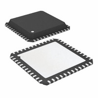
ATR2434-PLT Atmel, ATR2434-PLT Datasheet - Page 14

ATR2434-PLT
Manufacturer Part Number
ATR2434-PLT
Description
IC RADIO TXRX 2.4GHZ ISM 48QFN
Manufacturer
Atmel
Datasheet
1.ATR2434-PLT.pdf
(35 pages)
Specifications of ATR2434-PLT
Frequency
2.4GHz
Data Rate - Maximum
62.5kbps
Modulation Or Protocol
DSSS, GFSK
Applications
Gaming Devices, General Remote Control, HID
Power - Output
-0.5dBm
Sensitivity
-95dBm
Voltage - Supply
2.7 V ~ 3.6 V
Current - Receiving
57.7mA
Current - Transmitting
68mA
Data Interface
PCB, Surface Mount
Antenna Connector
PCB, Surface Mount
Operating Temperature
-40°C ~ 85°C
Package / Case
48-QFN Exposed Pad
Lead Free Status / RoHS Status
Contains lead / RoHS non-compliant
Memory Size
-
Table 8. Configuration
Table 9. SERDES Control
Table 10. Receive Interrupt Enable
14
Bit
7:5
4
3
2
1:0
Bit
7:4
3
2:0
Underflow B
7
7
7
Name
Reserved
SERDES
Enable
EOF Length
Name
Reserved
Receive
Invert
Transmit
Invert
Reserved
IRQ Pin
Select
Addr: 0x05
Addr: 0x06
Addr: 0x07
ATR2434 [Preliminary]
Overflow B
Reserved
6
6
6
Description
These bits are reserved and should be written with zeros.
The Receive Invert bit is used to invert the received data.
1 = Inverted over-the-air Receive data
0 = Non-inverted over-the-air Receive data
The Transmit Invert bit is used to invert the data that is to be transmitted.
1 = Inverted Transmit Data
0 = Non-inverted Transmit Data
This bit is reserved and should be written with zero.
The Interrupt Request Pin Select bits are used to determine the drive method of the IRQ pin.
11 = Open Drain (asserted = 0, deasserted = Hi-Z)
10 = Open Source (asserted = 1, deasserted = Hi-Z)
01 = CMOS (asserted = 1, deasserted = 0)
00 = CMOS Inverted (asserted = 0, deasserted = 1)
Description
These bits are reserved and should be written with zeros.
The SERDES Enable bit is used to switch between bit-serial mode and SERDES mode.
1 = SERDES enabled
0 = SERDES disabled, bit-serial mode enabled
When the SERDES is enabled data can be written to and read from the IC one byte at a time through the use
of the SERDES Data registers. The bit-serial mode requires bits to be written one bit at a time through the
use of the DIO/DIOVAL pins. It is recommended that the SERDES mode be used to avoid the need to
manage the timing required by the bit-serial mode.
The End of Frame Length bits are used to set the number of sequential bit times for an inter-frame gap
without valid data before an EOF event is generated. When in receive mode and a valid bit has been received
the EOF event can then be identified by the number of bit times that expire without correlating any new data.
The EOF event causes data to be moved to the proper SERDES Data Register and can also be used to
generate interrupts. If 0 is the EOF length, an EOF condition will occur at the first invalid bit after a valid
reception.
Reserved
EOF B
5
5
5
Receive
Full B
Invert
REG_SERDES_CTL
REG_RX_INT_EN
4
4
4
REG_CONFIG
Underflow A
SERDES
Transmit
Enable
Invert
3
3
3
Overflow A
Reserved
2
2
2
EOF Length
EOF A
1
1
1
IRQ Pin Select
Default: 0x01
Default: 0x03
Default: 0x00
4822D–ISM–10/04
Full A
0
0
0


