LMX9830SM/NOPB National Semiconductor, LMX9830SM/NOPB Datasheet - Page 43
LMX9830SM/NOPB
Manufacturer Part Number
LMX9830SM/NOPB
Description
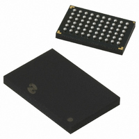
IC SRL PORT MOD BLUETOOTH 60FBGA
Manufacturer
National Semiconductor
Datasheet
1.LMX9830SMNOPB.pdf
(46 pages)
Specifications of LMX9830SM/NOPB
Frequency
2.4GHz
Data Rate - Maximum
704kbps
Modulation Or Protocol
Bluetooth v2.0, Class 2
Applications
PDA's, POS Terminals
Power - Output
0dBm
Sensitivity
-80dBm
Voltage - Supply
2.5 V ~ 3.6 V
Current - Receiving
65mA
Current - Transmitting
65mA
Data Interface
PCB, Surface Mount
Antenna Connector
PCB, Surface Mount
Operating Temperature
-40°C ~ 125°C
Package / Case
60-FBGA
Physical Interfaces
UART
Data Rate
704Kbps
Operating Temperature Range
-40°C To +125°C
Msl
MSL 4 - 72 Hours
Supply Voltage Range
1.6V To 3.6V
Frequency Max
2480MHz
Termination Type
SMD
Rohs Compliant
Yes
Filter Terminals
SMD
Frequency Min
2402MHz
Lead Free Status / RoHS Status
Lead free / RoHS Compliant
Memory Size
-
Lead Free Status / Rohs Status
Compliant
Other names
*LMX9830SM
*LMX9830SM/NOPB
LMX9830SM
*LMX9830SM/NOPB
LMX9830SM


PCB Land Pad Diameter
PCB Solder Mask Opening
PCB Finish (HASL details)
Stencil Aperture
Stencil Thickness
Solder Paste Used
Flux Cleaning Process
Reflow Profiles
Average Ramp-Up Rate (TsMAX to Tp)
Preheat:
Temperature Min (TsMIN)
Temperature Max (TsMAX)
Time (tsMIN to tsMAX)
Time maintained above:
Temperature (TL)
Time (tL)
Peak/Classification Temperature (Tp)
Time within 5°C of actual Peak Temperature (tp)
Ramp-Down Rate
Time 25 °C to Peak Temperature
Reflow Profiles
17.0 Soldering
The LMX9830 bumps are designed to melt as part of the Sur-
face Mount Assembly (SMA) process. In order to ensure
reflow of all solder bumps and maximum solder joint reliability
while minimizing damage to the package, recommended re-
flow profiles should be used.
Note 42: See IPC/JEDEC J-STD-020C, July 2004.
Note 43: All temperatures refer to the top side of the package, measured on the package body surface.
Parameter
Profile Feature
TABLE 40. Classification Reflow Profiles (Note 42), (Note 43)
FIGURE 21. Typical Reflow Profiles
TABLE 39. Soldering Details
43
Table 39, Table 40 and Figure 21provide the soldering details
required to properly solder the LMX9830 to standard PCBs.
The illustration serves only as a guide and National is not li-
able if a selected profile does not work.
See IPC/JEDEC J-STD-020C, July 2004 for more informa-
tion.
Defined by customer or manufacturing facility
Defined by customer or manufacturing facility
Defined by customer or manufacturing facility
See Figure 21
3°C/second maximum
6°C/second maximum
Value
13 mil
19 mil
17 mil
8 minutes maximum
5 mil
NOPB Assembly
20 – 40 seconds
60180 seconds
60150 seconds
See Figure 21
260 + 0°C
20180027
150°C
200°C
217°C
www.national.com
Related parts for LMX9830SM/NOPB
Image
Part Number
Description
Manufacturer
Datasheet
Request
R

Part Number:
Description:
Manufacturer:
National Semiconductor
Datasheet:

Part Number:
Description:
National Semiconductor [8-Bit D/A Converter]
Manufacturer:
National Semiconductor
Datasheet:
Part Number:
Description:
National Semiconductor [Media Coprocessor]
Manufacturer:
National Semiconductor
Datasheet:
Part Number:
Description:
Digitally Controlled Tone and Volume Circuit with Stereo Audio Power Amplifier, Microphone Preamp Stage and National 3D Sound
Manufacturer:
National Semiconductor
Datasheet:
Part Number:
Description:
Digitally Controlled Tone and Volume Circuit with Stereo Audio Power Amplifier, Microphone Preamp Stage and National 3D Sound
Manufacturer:
National Semiconductor
Datasheet:
Part Number:
Description:
AC97 Rev 2 Codec with Sample Rate Conversion and National 3D Sound
Manufacturer:
National Semiconductor
Part Number:
Description:
Manufacturer:
National Semiconductor
Datasheet:
Part Number:
Description:
Manufacturer:
National Semiconductor
Datasheet:
Part Number:
Description:
General Purpose, Low Voltage, Low Power, Rail-to-Rail Output Operational Amplifiers
Manufacturer:
National Semiconductor
Datasheet:
Part Number:
Description:
8-bit 20 MSPS flash A/D converter.
Manufacturer:
National Semiconductor
Datasheet:
Part Number:
Description:
Low Noise Quad Operational Amplifier
Manufacturer:
National Semiconductor
Datasheet:
Part Number:
Description:
Quad Differential Line Receivers
Manufacturer:
National Semiconductor
Datasheet:
Part Number:
Description:
Quad High Speed Trapezoidal? Bus Transceiver
Manufacturer:
National Semiconductor
Datasheet:
Part Number:
Description:
Dual Line Receiver
Manufacturer:
National Semiconductor
Datasheet: