LMX9830SM/NOPB National Semiconductor, LMX9830SM/NOPB Datasheet - Page 12
LMX9830SM/NOPB
Manufacturer Part Number
LMX9830SM/NOPB
Description
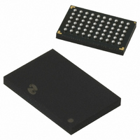
IC SRL PORT MOD BLUETOOTH 60FBGA
Manufacturer
National Semiconductor
Datasheet
1.LMX9830SMNOPB.pdf
(46 pages)
Specifications of LMX9830SM/NOPB
Frequency
2.4GHz
Data Rate - Maximum
704kbps
Modulation Or Protocol
Bluetooth v2.0, Class 2
Applications
PDA's, POS Terminals
Power - Output
0dBm
Sensitivity
-80dBm
Voltage - Supply
2.5 V ~ 3.6 V
Current - Receiving
65mA
Current - Transmitting
65mA
Data Interface
PCB, Surface Mount
Antenna Connector
PCB, Surface Mount
Operating Temperature
-40°C ~ 125°C
Package / Case
60-FBGA
Physical Interfaces
UART
Data Rate
704Kbps
Operating Temperature Range
-40°C To +125°C
Msl
MSL 4 - 72 Hours
Supply Voltage Range
1.6V To 3.6V
Frequency Max
2480MHz
Termination Type
SMD
Rohs Compliant
Yes
Filter Terminals
SMD
Frequency Min
2402MHz
Lead Free Status / RoHS Status
Lead free / RoHS Compliant
Memory Size
-
Lead Free Status / Rohs Status
Compliant
Other names
*LMX9830SM
*LMX9830SM/NOPB
LMX9830SM
*LMX9830SM/NOPB
LMX9830SM


www.national.com
Baud Rate
Flow Control
Parity
Stop Bits
Data Bits
OKI
MSM7717
Motorola MC145483
(Note 25)
OKI
MSM7717
Motorola MC145483
(Note 26)
Winbond W681310
Winbond W681360
PCM slave (Note 27)
9.3 AUDIO PORT
9.3.1 Advanced Audio Interface
The Advanced Audio Interface (AAI) is an advanced version
of the Synchronous Serial Interface (SSI) that provides a full-
duplex communications port to a variety of industry-standard
13/14/15/16-bit linear or 8-bit log PCM codecs, DSPs, and
other serial audio devices.
The interface allows the support one codec or interface. The
firmware selects the desired audio path and interface config-
uration by a parameter that is located in RAM (imported from
Note 24: For supported frequencies see Table 20.
Note 25: Due to internal clock divider limitations the optimum of 512 kHz, 8 kHz can not be reached. The values are set to the best possible values. The clock
mismatch does not result in any discernible loss in audio quality.
Note 26: Due to internal clock divider limitations the optimum of 512 kHz, 8 kHz can not be reached. The values are set to the best possible values. The clock
mismatch does not result in any discernible loss in audio quality.
Note 27: In PCM slave mode, parameters are stored in NVS. Bit clock and frame clock must be generated by the host interface.
PCM slave configuration example: PCM slave uses the slot
0, 1 slot per frame, 16 bit linear mode, long frame sync, normal
frame sync. In this case, 0x03E0 should be stored in NVS.
See “LMX9830 Software Users Guide” for more details.
9.4 AUXILIARY PORTS
9.4.1 RESET#
There are two reset inputs: RESET_RA# for the radio and
RESET_BB# for the baseband. Both are active low.
There is also a reset output, B_RESET_RA# (Buffered Radio
Reset) active low. This output follows input RESET_RA#.
Audio setting
Item
2.4 to 921.6 kbits/s
RTS#/CTS# or None
Odd, Even, None
1,2
8
Advanced audio
Advanced audio
Advanced audio
Advanced audio
Advanced audio
Advanced audio
Advanced audio
Interface
interface
interface
interface
interface
interface
interface
interface
Range
(Note 24)
(Note 24)
13 MHz
13 MHz
13 MHz
TABLE 12. Audio Path Configuration
TABLE 11. UART Operation Modes
Freq
ANY
ANY
Either configured by option pins, NVS
parameter or auto baud rate detection
RTS#/CTS#
None
1
8
A-law and μ-law
8-bit log PCM
8-bit log PCM
8 bit log PCM
(a-law only)
13-bit linear
(a-law only)
13-bit linear
13-bit linear
Default at Power-Up
8/16 bits
Format
12
non-volatile storage or programmed during boot-up). The au-
dio path options include the Motorola MC145483 codec, the
OKI MSM7717 codec, the Winbond W681360/W681310
codecs and the PCM slave through the AAI.
In case an external codec or DSP is used the LMX9830 audio
interface generates the necessary bit and frame clock driving
the interface.
Table 12 summarizes the audio path selection and the con-
figuration of the audio interface at the specific modes.
The LMX9830 supports one SCO link.
When RESET_RA# is released, going high, B_RESET_RA#
stays low until the clock has started.
Please see Section 9.5 SYSTEM POWER UP for details.
9.4.2 General Purpose I/Os
The LMX9830 offers 3 pins which either can be used as indi-
cation and configuration pins or can be used for General
Purpose functionality. The selection is made out of settings
derived out of the power up sequence.
In General Purpose configuration the pins are controlled hard-
ware specific commands giving the ability to set the direction,
set them to high or low or enable a weak pull-up.
128 - 1024 kHz
AAI Bit Clock AAI Frame Clock
480 kHz
480 kHz
520 kHz
520 kHz
520 kHz
520 kHz
2.4 to 921.6 kbits/s
RTS#/CTS#
None
1
8
8 kHz
8 kHz
8 kHz
8 kHz
8 kHz
8 kHz
8 kHz
With Auto-Detect
AAI Frame Sync
Pulse Length
8/16 Bits
14 Bits
13 Bits
14 Bits
13 Bits
14 Bits
13 Bits
Related parts for LMX9830SM/NOPB
Image
Part Number
Description
Manufacturer
Datasheet
Request
R

Part Number:
Description:
Manufacturer:
National Semiconductor
Datasheet:

Part Number:
Description:
National Semiconductor [8-Bit D/A Converter]
Manufacturer:
National Semiconductor
Datasheet:
Part Number:
Description:
National Semiconductor [Media Coprocessor]
Manufacturer:
National Semiconductor
Datasheet:
Part Number:
Description:
Digitally Controlled Tone and Volume Circuit with Stereo Audio Power Amplifier, Microphone Preamp Stage and National 3D Sound
Manufacturer:
National Semiconductor
Datasheet:
Part Number:
Description:
Digitally Controlled Tone and Volume Circuit with Stereo Audio Power Amplifier, Microphone Preamp Stage and National 3D Sound
Manufacturer:
National Semiconductor
Datasheet:
Part Number:
Description:
AC97 Rev 2 Codec with Sample Rate Conversion and National 3D Sound
Manufacturer:
National Semiconductor
Part Number:
Description:
Manufacturer:
National Semiconductor
Datasheet:
Part Number:
Description:
Manufacturer:
National Semiconductor
Datasheet:
Part Number:
Description:
General Purpose, Low Voltage, Low Power, Rail-to-Rail Output Operational Amplifiers
Manufacturer:
National Semiconductor
Datasheet:
Part Number:
Description:
8-bit 20 MSPS flash A/D converter.
Manufacturer:
National Semiconductor
Datasheet:
Part Number:
Description:
Low Noise Quad Operational Amplifier
Manufacturer:
National Semiconductor
Datasheet:
Part Number:
Description:
Quad Differential Line Receivers
Manufacturer:
National Semiconductor
Datasheet:
Part Number:
Description:
Quad High Speed Trapezoidal? Bus Transceiver
Manufacturer:
National Semiconductor
Datasheet:
Part Number:
Description:
Dual Line Receiver
Manufacturer:
National Semiconductor
Datasheet: