LMX9830SM/NOPB National Semiconductor, LMX9830SM/NOPB Datasheet - Page 11
LMX9830SM/NOPB
Manufacturer Part Number
LMX9830SM/NOPB
Description
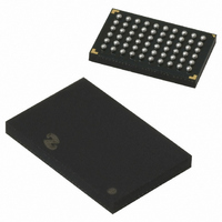
IC SRL PORT MOD BLUETOOTH 60FBGA
Manufacturer
National Semiconductor
Datasheet
1.LMX9830SMNOPB.pdf
(46 pages)
Specifications of LMX9830SM/NOPB
Frequency
2.4GHz
Data Rate - Maximum
704kbps
Modulation Or Protocol
Bluetooth v2.0, Class 2
Applications
PDA's, POS Terminals
Power - Output
0dBm
Sensitivity
-80dBm
Voltage - Supply
2.5 V ~ 3.6 V
Current - Receiving
65mA
Current - Transmitting
65mA
Data Interface
PCB, Surface Mount
Antenna Connector
PCB, Surface Mount
Operating Temperature
-40°C ~ 125°C
Package / Case
60-FBGA
Physical Interfaces
UART
Data Rate
704Kbps
Operating Temperature Range
-40°C To +125°C
Msl
MSL 4 - 72 Hours
Supply Voltage Range
1.6V To 3.6V
Frequency Max
2480MHz
Termination Type
SMD
Rohs Compliant
Yes
Filter Terminals
SMD
Frequency Min
2402MHz
Lead Free Status / RoHS Status
Lead free / RoHS Compliant
Memory Size
-
Lead Free Status / Rohs Status
Compliant
Other names
*LMX9830SM
*LMX9830SM/NOPB
LMX9830SM
*LMX9830SM/NOPB
LMX9830SM


Supplier
Supply Voltage (Note 22)
Interface
Memory Size
Clock Rate (Note 22)
Access
Supplier
Supply Voltage(Note 23)
Interface
Memory Size
Clock Rate (Note 23)
Access
9.1.6 External memory interfaces
As the LMX9830 is a ROM based device with no on-chip non
volatile storage, the operation parameters will be lost after a
power cycle or hardware reset. In order to prevent re initial-
izing such parameters, patches or even user data, the
LMX9830 offers two interfaces to connect an external EEP-
ROM to the device:
•
•
The selection of the interface is done during start up based
on the option pins. See Table 16 for the option pin descrip-
tions.
Note 22: Parameter range reduced to requirements of National reference design.
9.1.8 Access.bus Interface
In case the firmware is configured by the option pins to use
an access.bus or I
activate that interface and try to read out data from the EEP-
ROM. The external memory needs to be compatible to the
reference listed in Table 10.
Note 23: Parameter range reduced to requirements of National reference design.
9.2 TRANSPORT PORT - UART
The LMX9830 provides one Universal Asynchronous Receiv-
er Transmitter (UART). The UART interface consists out of
Receive (RX), Transmit (TX), Ready-to-Send (RTS) and
Clear-to-Send signals. RTS and CTS are used for hardware
handshaking between the host and the LMX9830. Since the
LMX9830 acts as gateway between the bluetooth and the
UART interface, National recommends to use the handshak-
ing signals especially for transparent operation. In case two
signals are used CTS needs to be pulled to GND. Please refer
also to “LMX9830 Software User’s Guide” for detailed infor-
mation on 2-wire operation.
The UART interface supports formats of 8-bit data with or
without parity, with one or two stop bits. It can operate at
standard baud rates from 2400bits/s up to a maximum baud
μ-wire/SPI
Access.bus (I
2
C compatible)
2
C compatible EEPROM, the LMX9830 will
Parameter
Parameter
TABLE 9. M95640-S EEPROM 8k x 8
TABLE 10. 24C64 EEPROM 8kx8
ST Microelectronics
1.8 - 3.6V
SPI compatible (positive clock SPI Modes)
8k x 8, 64 kbit
2 MHz
Byte and Page Write (up to 32 bytes)
Atmel
2.7 - 5.5 V
2 wire serial interface
8K x 8, 64 kbit
100 kHz
32 Byte Page Write Mode
11
9.1.7 µ-wire/SPI interface
In case the firmware is configured by the option pins to use a
µ-wire/SPI EEPROM, the LMX9830 will activate that interface
and try to read out data from the EEPROM. The external
memory needs to be compatible to the reference listed in
Table 10. The largest size EEPROM supported is limited by
the addressing format of the selected NVM.
The device must have a page size equal to N x 32 bytes.
The firmware requires that the EEPROM supports Page write.
Clock must be HIGH when idle.
The largest size EEPROM supported is limited by the ad-
dressing format of the selected NVM. The device must have
a page size equal to N x 32 bytes.
The device uses a 16 bit address format. The device address
must be “000”.
rate of 921.6 kbits/s. DMA transfers are supported to allow for
fast processor independent receive and transmit operation.
The UART baudrate is configured during startup by checking
option pins OP3, OP4 and OP5 for reference clock and bau-
drate. In case Auto baud rate detect is chosen, the firmware
check the NVS area if a valid UART baudrate has been stored
in a previous session. In case, no useful value can be found
the device will switch to auto baud rate detection and wait for
an incoming reference signal.
The UART offers wakeup from the power save modes via the
multi-input wakeup module. When the LMX9830 is in low
power mode, RTS# and CTS# can function as Host_WakeUp
and Bluetooth_WakeUp respectively. Table 11 represents the
operational modes supported by the firmware for implement-
ing the transport via the UART.
Value
Value
www.national.com
Related parts for LMX9830SM/NOPB
Image
Part Number
Description
Manufacturer
Datasheet
Request
R

Part Number:
Description:
Manufacturer:
National Semiconductor
Datasheet:

Part Number:
Description:
National Semiconductor [8-Bit D/A Converter]
Manufacturer:
National Semiconductor
Datasheet:
Part Number:
Description:
National Semiconductor [Media Coprocessor]
Manufacturer:
National Semiconductor
Datasheet:
Part Number:
Description:
Digitally Controlled Tone and Volume Circuit with Stereo Audio Power Amplifier, Microphone Preamp Stage and National 3D Sound
Manufacturer:
National Semiconductor
Datasheet:
Part Number:
Description:
Digitally Controlled Tone and Volume Circuit with Stereo Audio Power Amplifier, Microphone Preamp Stage and National 3D Sound
Manufacturer:
National Semiconductor
Datasheet:
Part Number:
Description:
AC97 Rev 2 Codec with Sample Rate Conversion and National 3D Sound
Manufacturer:
National Semiconductor
Part Number:
Description:
Manufacturer:
National Semiconductor
Datasheet:
Part Number:
Description:
Manufacturer:
National Semiconductor
Datasheet:
Part Number:
Description:
General Purpose, Low Voltage, Low Power, Rail-to-Rail Output Operational Amplifiers
Manufacturer:
National Semiconductor
Datasheet:
Part Number:
Description:
8-bit 20 MSPS flash A/D converter.
Manufacturer:
National Semiconductor
Datasheet:
Part Number:
Description:
Low Noise Quad Operational Amplifier
Manufacturer:
National Semiconductor
Datasheet:
Part Number:
Description:
Quad Differential Line Receivers
Manufacturer:
National Semiconductor
Datasheet:
Part Number:
Description:
Quad High Speed Trapezoidal? Bus Transceiver
Manufacturer:
National Semiconductor
Datasheet:
Part Number:
Description:
Dual Line Receiver
Manufacturer:
National Semiconductor
Datasheet: