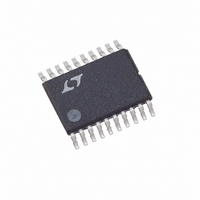
LT5503EFE#TR Linear Technology, LT5503EFE#TR Datasheet

LT5503EFE#TR
Specifications of LT5503EFE#TR
Available stocks
Related parts for LT5503EFE#TR
LT5503EFE#TR Summary of contents
Page 1
... Wireless Local Loop (WLL) ■ PCS Wireless Data ■ MMDS , LT, LTC and LTM are registered trademarks of Linear Technology Corporation. All other trademarks are the property of their respective owners. *Patent Pending U TYPICAL APPLICATIO 2.45GHz Transmitter Application, Carrier for Modulator Generated by Upmixer V ...
Page 2
... ORDER I FOR ATIO LEAD FREE FINISH TAPE AND REEL LT5503EFE#PBF LT5503EFE#TRPBF Consult LTC Marketing for parts specified with wider operating temperature ranges. Consult LTC Marketing for information on nonstandard lead based finish parts. For more information on lead free part marking, go to: For more information on tape and reel specifications, go to: ...
Page 3
ELECTRICAL CHARACTERISTICS V = 3VDC, 2.4GHz matching, MODEN = High, GC1 = GC2 = Low, T CC1 100kHz CW signal at 1V differential, Q leads I by 90°, unless otherwise noted. (Test circuit shown in Figure 2.) (Note 3) P-P ...
Page 4
LT5503 ELECTRICAL CHARACTERISTICS = 3VDC, 2.4GHz matching, MIXEN = High, DMODE = Low (LO2 ÷ 2 mode CC2 2075MHz at –12dBm. MIXRFOUT measured at 2450MHz, unless otherwise noted. (Test circuit shown in Figure 2.) (Note 3) PARAMETER Mixer ...
Page 5
W U TYPICAL PERFOR A CE CHARACTERISTICS V = 3VDC, 2.4GHz matching, MODEN = high, GC1 = GC2 = low (max gain), T CC1 (Q– 100kHz sine at 1V differential, Q leads I by 90°, unless otherwise noted. ...
Page 6
LT5503 W U TYPICAL PERFOR A CE CHARACTERISTICS 2.4GHz matching, MODEN = high, GC1 = GC2 = low (max gain), MODRFIN = 2.45GHz, (I–I differential, Q leads I by 90°, unless otherwise noted. (Test circuit shown in Figure 2.) SSB ...
Page 7
W U TYPICAL PERFOR A CE CHARACTERISTICS V = 3VDC, MODEN = high 25°C, P CC1 A unless otherwise noted. (Test circuit shown in Figure 2.) Output Power vs Frequency 1.2GHz Matching 0 GC2, GC1 = 00 –2 ...
Page 8
LT5503 W U TYPICAL PERFOR A CE CHARACTERISTICS 2.4GHz matching, MIXEN = high, DMODE = low (LO2 ÷ 2 mode), LO2IN = 750MHz at –18dBm, LO1IN = 2075MHz. MIXRFOUT measured at 2450MHz, unless otherwise noted. (Test circuit shown in Figure ...
Page 9
W U TYPICAL PERFOR A CE CHARACTERISTICS = 3VDC, MIXEN = high, DMODE = low (LO2 ÷ 2mode CC2 RF Output Power and LO1 Feedthrough 1.9GHz Matching –12 OUTPUT POWER –14 –16 –18 LO1 FEEDTHROUGH –20 LO2IN = ...
Page 10
LT5503 CTIO S – BQ (Pin 1): Negative Baseband Input Pin of the Modulator Q-Channel. This pin is internally biased to 1.4V, but can also be overdriven with an external DC voltage greater than 1.4V, ...
Page 11
W BLOCK DIAGRA V MOD MODIN V LO1 CC LO1 + – – V-I V-I 5 VGA 6 CONTROL 90° RF 0° LOCIC BUFFER 4 MODULATOR BIAS ...
Page 12
LT5503 TEST CIRCUIT MODRFIN V CC1 LO1IN V CC2 C2, C3, C7 C10 C23 C11 L4 L5,L6 T1 Figure 1. Test Schematic for 1.2GHz, 1.9GHz and 2.4GHz Applications 12 ...
Page 13
U U APPLICATIO S I FOR ATIO The LT5503 consists of a direct quadrature modulator and a mixer. The mixer operates over the range of 1.7GHz to 2.7GHz, and the modulator operates with an output range of 1.2GHz to 2.7GHz. ...
Page 14
LT5503 U U APPLICATIO S I FOR ATIO AC-Coupled Baseband . Figure 3 shows the simplified circuit schematic of a high-pass AC-coupled baseband interface LT5503 CPL BI I 0.8pF 18k C – CPL 0.8pF C ...
Page 15
U U APPLICATIO S I FOR ATIO Pin 16 should be connected externally to V low value series resistor (47Ω typical). To assure proper output power control, a good, local high frequency AC ground for Pin 16 is essential. The ...
Page 16
LT5503 U U APPLICATIO S I FOR ATIO EVALUATION BOARD Figure 6 shows the circuit schematic of the evaluation board. The MODRFIN, MODRFOUT and MIXRFOUT ports are matched to 50Ω at 2.45GHz. The LO1IN port is matched to 50Ω at ...
Page 17
U U APPLICATIO S I FOR ATIO E4 V CC4 C33 4.7μ Q-IN 7 R14 U2-1 R3 R13 510Ω LT1807 56Ω 510Ω – R17 4 6 510Ω 1% C35, 39pF C37, 1pF R19 ...
Page 18
LT5503 U U APPLICATIO S I FOR ATIO GND MODRFIN LO1IN QIN IIN LT1807 LT5503 IC GND V CC2 MIXRFOUT Figure 7. LT5503 Evaluation Board Layout V CC4 V CC1 LT1807 V4 MODRFOUT LO2IN ...
Page 19
... SIGNAL GENERATOR 1 LO1IN POWER SUPPLY 2 Information furnished by Linear Technology Corporation is believed to be accurate and reliable. However, no responsibility is assumed for its use. Linear Technology Corporation makes no represen- tation that the interconnection of its circuits as described herein will not infringe on existing patent rights QIN ...
Page 20
... Integrated LO Buffer Precision V Offset Control, Adjustable Gain and Offset Voltage OUT www.linear.com ● 3.86 (.152 6.40 2.74 (.252) (.108) BSC 1.20 (.047) MAX 0.05 – 0.15 (.002 – .006) FE20 (CB) TSSOP 0204 LT 1107 • PRINTED IN USA © LINEAR TECHNOLOGY CORPORATION 2001 5503f ...


