DM303006 Microchip Technology, DM303006 Datasheet - Page 43
DM303006
Manufacturer Part Number
DM303006
Description
KIT EVALUATION KEELOQ
Manufacturer
Microchip Technology
Series
KEELOQ®r
Type
KeeLoq®r
Specifications of DM303006
Silicon Manufacturer
Microchip
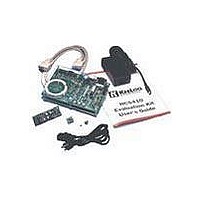
Kit Contents
Main Board, 2 Transmitters, Cables And Power Supply
Tool / Board Applications
General Purpose MCU, MPU, DSP, DSC
For Use With
KeeLoq
Lead Free Status / RoHS Status
Request inventory verification / Request inventory verification
For Use With/related Products
Keeloq Encoders & Decoders
Lead Free Status / RoHS Status
Lead free / RoHS Compliant, Request inventory verification / Request inventory verification


D.1
FIGURE D-1:
D.1.1
Power Supply, 9V – 15V input.
AC/DC input, (NO polarity)
D.1.2
9V battery clip
Polarity is dictated by the clip mechanics.
A diode (CR2) protects from reversed polarity insertion
and inverse currents should the power supply be used
at the same time.
D.1.3
Red +5V TP and corresponding Black GND TP
Provides regulated 5V output for proto area.
The voltage regulator (VR1) is capable of 100 mA max.
The current draw of the prototype area must be limited
to keep total board consumption (varying with the num-
ber 100 mA limit.
DS41155A-page 41
M
J1-power
supply
BT1- battery clip
Connectors Layout
J1- POWER SUPPLY
BT1- BATTERY CLIP
TEST POINTS ON PROTOTYPING
AREA
CONNECTORS AND TEST POINTS LAYOUT
J3-TX prog.
J2-RS-232
Appendix D: Connectors
JP2-transponder coil
J5-ICSP
J4-ICD
D.1.4
Hardware handshake is not used in revision (v.3.00.00)
of the firmware
Programming
Socket
Pin
1
2
3
4
5
6
7
8
9
J6-LCD
GND
J2- RS-232 (9-PIN)
+5V
K
EE
L
OQ
Signal
GND
CTS
RTS
NC
RX
NC
NC
NC
TX
2001 Microchip Technology Inc.
®
EVALUATION KIT
II USER’S GUIDE
MCU pin
RC6
RC7
RC5
RC0
V
—
—
—
—
SS
Related parts for DM303006
Image
Part Number
Description
Manufacturer
Datasheet
Request
R

Part Number:
Description:
Manufacturer:
Microchip Technology Inc.
Datasheet:
Part Number:
Description:
Manufacturer:
Microchip Technology Inc.
Datasheet:
Part Number:
Description:
Manufacturer:
Microchip Technology Inc.
Datasheet:
Part Number:
Description:
Manufacturer:
Microchip Technology Inc.
Datasheet:
Part Number:
Description:
Manufacturer:
Microchip Technology Inc.
Datasheet:
Part Number:
Description:
Manufacturer:
Microchip Technology Inc.
Datasheet:
Part Number:
Description:
Manufacturer:
Microchip Technology Inc.
Datasheet:
Part Number:
Description:
Manufacturer:
Microchip Technology Inc.
Datasheet: