DM303006 Microchip Technology, DM303006 Datasheet - Page 20
DM303006
Manufacturer Part Number
DM303006
Description
KIT EVALUATION KEELOQ
Manufacturer
Microchip Technology
Series
KEELOQ®r
Type
KeeLoq®r
Specifications of DM303006
Silicon Manufacturer
Microchip
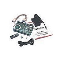
Kit Contents
Main Board, 2 Transmitters, Cables And Power Supply
Tool / Board Applications
General Purpose MCU, MPU, DSP, DSC
For Use With
KeeLoq
Lead Free Status / RoHS Status
Request inventory verification / Request inventory verification
For Use With/related Products
Keeloq Encoders & Decoders
Lead Free Status / RoHS Status
Lead free / RoHS Compliant, Request inventory verification / Request inventory verification


6.0
The evaluation kit demonstration transmitters support
any 8- or 14-pin DIP K
Figure 6-1.
The encoder socket U2 supports 8-pin and 14-pin
encoders inserted with pin 1 in the corresponding pin 1
of the 14-pin socket (Figure 6-1). The demo transmitter
PCB leaves pins 5 through 9 unconnected to accom-
modate the different and sometimes conflicting pin
functionalities on the HCS473, HCS370 and future
products. The user is advised to avoid hand contact
with those pins as there may be only weak internal pull
ups on the most sensitive inputs. Inadvertent input sig-
nals could trigger unexpected responses from the
device confusing the demonstration.
The four buttons (S0..S3) on the demonstration trans-
mitters are connected to the appropriate inputs on the
encoder (S0 through S3). The user may activate any
combination of encoder inputs transmitting any of the
15 possible function codes. The RFEN output is not
used by the demonstration transmitter and should be
disabled as several encoders share its output with a
button input. If enabled, a button input may be lost.
FIGURE 6-1:
DS41155A-page 18
M
DEMONSTRATION
TRANSMITTERS
K
EE
Programming Connector
L
OQ
EE
L
DEMONSTRATION TRANSMITTER
OQ
Demonstration Transmitters
encoder as shown in
2 x 3V Lithium battery
LED control jumper
The RF oscillator uses a Surface Acoustic Wave
(SAW) resonator to operate at 433.92 MHz. Note that
this is not sufficient to ensure compliance with EC and/
or FCC regulations.
Jumper JP1 connects the DATA output of the encoder
to the RF transmitter modulator circuit input.
removed, it can be used to monitor the digital encoder
output while the RF section is disabled.
LED
pin 1
K
EE
L
OQ
Encoder socket
fits 8- and 14-pin
RF output jumper
2001 Microchip Technology Inc.
®
EVALUATION KIT
II USER’S GUIDE
If
Related parts for DM303006
Image
Part Number
Description
Manufacturer
Datasheet
Request
R

Part Number:
Description:
Manufacturer:
Microchip Technology Inc.
Datasheet:
Part Number:
Description:
Manufacturer:
Microchip Technology Inc.
Datasheet:
Part Number:
Description:
Manufacturer:
Microchip Technology Inc.
Datasheet:
Part Number:
Description:
Manufacturer:
Microchip Technology Inc.
Datasheet:
Part Number:
Description:
Manufacturer:
Microchip Technology Inc.
Datasheet:
Part Number:
Description:
Manufacturer:
Microchip Technology Inc.
Datasheet:
Part Number:
Description:
Manufacturer:
Microchip Technology Inc.
Datasheet:
Part Number:
Description:
Manufacturer:
Microchip Technology Inc.
Datasheet: