SI4136M-EVB Silicon Laboratories Inc, SI4136M-EVB Datasheet - Page 17
SI4136M-EVB
Manufacturer Part Number
SI4136M-EVB
Description
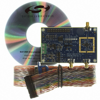
BOARD EVALUATION FOR SI4136
Manufacturer
Silicon Laboratories Inc
Type
Synthesizerr
Specifications of SI4136M-EVB
Lead Free Status / RoHS Status
Contains lead / RoHS non-compliant
For Use With/related Products
SI4136
Lead Free Status / Rohs Status
Lead free / RoHS Compliant
Other names
336-1119


Table 6 summarizes the characteristics of the IF VCO.
As
frequencies in a 30 MHz band between 735 MHz and
765 MHz is desired. The center frequency should be
defined as midway between the two extremes, or
750 MHz. The PLL will be able to adjust the VCO output
frequency ±5% of the center frequency, or ±37.5 MHz of
750 MHz
788 MHz). The IF VCO has a C
6.9 nH inductance (correct to two digits) in parallel with
this capacitance will yield the desired center frequency.
An external inductance of 4.8 nH should be connected
between IFLA and IFLB, as shown in Figure 14. This, in
addition to 2.1 nH of package inductance, will present
the
manufacturing, the external inductance can vary ±10%
of its nominal value and the Si4136 will correct for the
variation with the self-tuning algorithm.
For more information on designing the external trace
inductor, please refer to Application Note 31.
f
Table 6. Si4136-BT/GT VCO Characteristics
CEN
VCO Fcen Range
IF
Figure 14. Example of IF External Inductor
a
correct
=
design
---------------------------------------------
2 L
526
Min
(i.e.,
(MHz)
Si4136
TOT
total
1
Max
952
from
example,
C
NOM
inductance
Cnom
(pF)
L
L
6.5
approximately
PKG
PKG
2
=
2
----------------------------------------------------------------------
2
suppose
Lpkg
(nH)
2.1
L
NOM
PKG
to
+
of 6.5 pF, and a
Lext Range
the
Min
1
2.2
L
IFLA
IFLB
EXT
L
713 MHz
EXT
synthesizing
(nH)
C
VCO.
12.0
Max
NOM
Rev. 1.41
to
In
2.3. Self-Tuning Algorithm
The self-tuning algorithm is initiated immediately
following power-up of a PLL or, if the PLL is already
powered, following a change in its programmed output
frequency. This algorithm attempts to tune the VCO so
that its free-running frequency is near the desired output
frequency. In so doing, the algorithm will compensate
for manufacturing tolerance errors in the value of the
external inductance connected to the IF VCO. It will also
reduce the frequency error for which the PLL must
correct to get the precise desired output frequency. The
self-tuning algorithm will leave the VCO oscillating at a
frequency in error by somewhat less than 1% of the
desired output frequency.
After self-tuning, the PLL controls the VCO oscillation
frequency. The PLL will complete frequency locking,
eliminating any remaining frequency error. Thereafter, it
will maintain frequency-lock, compensating for effects
caused by temperature and supply voltage variations.
The Si4136’s self-tuning algorithm will compensate for
component value errors at any temperature within the
specified temperature range. However, the ability of the
PLL to compensate for drift in component values that
occur
inductances with temperature coefficients around ±150
ppm/°C, the PLL will be able to maintain lock for
changes in temperature of approximately ±30°C.
Applications where the PLL is regularly powered-down
or the frequency is periodically reprogrammed minimize
or eliminate the potential effects of temperature drift
because the VCO is re-tuned in either case. In
applications where the ambient temperature can drift
substantially after self-tuning, it may be necessary to
monitor the lock-detect bar (LDETB) signal on the
AUXOUT pin to determine whether a PLL is about to
run out of locking capability. (See “2.9. Auxiliary Output
(AUXOUT)” for how to select LDETB.) The LDETB
signal will be low after self-tuning has completed but will
rise when either the IF or RF PLL nears the limit of its
compensation range. (LDETB will also be high when
either PLL is executing the self-tuning algorithm.) The
output frequency will still be locked when LDETB goes
high, but the PLL will eventually lose lock if the
temperature continues to drift in the same direction.
Therefore, if LDETB goes high both the IF and RF PLLs
should promptly be re-tuned by initiating the self-tuning
algorithm.
2.4. Output Frequencies
The IF and RF output frequencies are set by
programming the R- and N-Divider registers. Each PLL
has its own R and N registers so that each can be
after
self-tuning
Si4136/Si4126
is
limited.
For
external
17
Related parts for SI4136M-EVB
Image
Part Number
Description
Manufacturer
Datasheet
Request
R

Part Number:
Description:
BOARD EVALUATION FOR SI4136
Manufacturer:
Silicon Laboratories Inc
Datasheet:

Part Number:
Description:
IC WLAN SAT RADIO 24TSSOP
Manufacturer:
Silicon Laboratories Inc
Datasheet:

Part Number:
Description:
IC SYNTHESIZER RF1/RF2/IF 28QFN
Manufacturer:
Silicon Laboratories Inc
Datasheet:

Part Number:
Description:
IC SYNTHESIZER RF1/RF2/IF 28MLP
Manufacturer:
Silicon Laboratories Inc
Datasheet:

Part Number:
Description:
IC SYNTH WLAN SAT/RADIO 28MLP
Manufacturer:
Silicon Laboratories Inc
Datasheet:
Part Number:
Description:
IC SYNTH RF1/RF2/IF 24TSSOP
Manufacturer:
Silicon Laboratories Inc
Datasheet:

Part Number:
Description:
SYNTH WLAN SAT RADIO(RF1/RF2/IF)
Manufacturer:
Silicon Laboratories Inc
Datasheet:
Part Number:
Description:
SYNTH WLAN SAT RADIO(RF1/RF2/IF)
Manufacturer:
Silicon Laboratories Inc
Datasheet:
Part Number:
Description:
RF Wireless Misc (RF1/RF2/IF)
Manufacturer:
Silicon Laboratories Inc
Datasheet:
Part Number:
Description:
SMD/C�/SINGLE-ENDED OUTPUT SILICON OSCILLATOR
Manufacturer:
Silicon Laboratories Inc
Part Number:
Description:
Manufacturer:
Silicon Laboratories Inc
Datasheet:
Part Number:
Description:
N/A N/A/SI4010 AES KEYFOB DEMO WITH LCD RX
Manufacturer:
Silicon Laboratories Inc
Datasheet:
Part Number:
Description:
N/A N/A/SI4010 SIMPLIFIED KEY FOB DEMO WITH LED RX
Manufacturer:
Silicon Laboratories Inc
Datasheet: