EVAL-869-ES Linx Technologies Inc, EVAL-869-ES Datasheet - Page 2
EVAL-869-ES
Manufacturer Part Number
EVAL-869-ES
Description
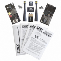
KIT EVAL BASIC 869MHZ ES SERIES
Manufacturer
Linx Technologies Inc
Series
ESr
Type
Transmitter, Receiverr
Specifications of EVAL-869-ES
Frequency
869MHz
Product
RF Development Tools
Maximum Frequency
868 MHz
Supply Voltage (max)
5 V
Lead Free Status / RoHS Status
Lead free / RoHS Compliant
For Use With/related Products
Linx OEM Module
Lead Free Status / Rohs Status
Lead free / RoHS Compliant


ES TRANSMITTER EVALUATION BOARD
ES RECEIVER EVALUATION BOARD
Page 2
2
1.
2.
3.
4.
5.
6.
7.
8.
9.
1.
2.
3.
4.
5.
6.
7.
8.
9.
Batteries - 3VDC (use 2 AAA style batteries only)
Power Switch
Continuous ON Switches
Momentary Pushbuttons - S0 (D0), S1 (D1)
Prototyping Area
Breakout Header
Reverse-Polarity SMA Antenna Connector
ES Series Transmitter Module
MS Series Encoder
Battery - 9VDC
Power Switch
Prototyping Area
Breakout Header
LR Series Receiver Module
MS Series Decoder
Reverse-Polarity SMA Antenna Connector
LED - D1
Buzzer - D0
1
1
3
2
4
3
5
4
6
6
8
5
7
7
8
9
9
THEORY OF OPERATION
USING THE KIT
DEVELOPMENT USING THE PROTOTYPING AREA
TRANSMITTER EVALUATION BOARD
RECEIVER EVALUATION BOARD
The transmitter board is powered by two AAA batteies. It has two SPST
pushbutton switches, the state of which is encoded into a data stream using a
using a Linx MS Series encoder. If a switch is closed, the transmitter will be
enabled while the encoder captures the pushbutton states for encoding and
transmission. The encoder will power down the transmitter when the button is
released. Only the two switches that control the LED and buzzer on the receiver
board have been populated, but if it is desired to use all eight data lines, then the
Omron B3S-1002 or equivalent switches can be used. All of the data lines have
been wired out to the header to the right of the prototyping area and can be
accessed for use with other switches, contacts, or microcontrollers.
The receiver board is powered by a 9V battery. The ES Series receiver exhibits
a sensitivity of greater than -97dBm, so under optimum line-of-sight conditions,
the transmitter / receiver link can operate over distances of up to 1,000 feet. The
data recovered by the ES Series receiver is decoded by a MS Series decoder,
and the data lines are updated to match the state of the data lines (or
pushbuttons) on the transmitter board. To demonstrate this, one data line is used
to drive a LED while another is used to activate a buzzer. Switching transistors
are used as drive buffers, as the Holtek decoder cannot directly source the
current necessary to operate these devices. This board also has a prototyping
area with all of the receiver and decoder lines brought out to a header.
Using the kit is straightforward. Simply attach the antennas, turn on the power,
and press one or both of the buttons on the transmitter board. When S0 is
pressed, the buzzer will sound; when S1 is pressed, the LED will turn on.
In addition to their evaluation functions, the boards may also be used for actual
product development. They feature a prototyping area to facilitate the addition of
application-specific circuitry. This area has a connection to V
ground at the bottom that can be used to power the added circuitry.
NOTE: If added circuitry requires a higher current than can be provided by the batteries,
the batteries must be removed and the board powered from an external source. The 9V
battery on the receiver board is regulated to 5V and has approximately 50mA available for
external circuitry.
The holes are plated and set at 0.100” on center with a 0.040” diameter, making
it easy to add most industry-standard SIP and DIP packages to the board.
On the transmitter board, the data lines from the encoder and the PDN, CLK,
CLKSE, and LO_V_D lines from the transmitter have been wired out to a row of
plated holes on the right side of the prototyping area. On the receiver board, the
data lines from the decoder plus the RSSI, PDN, AUDIO, A_REF and DATA lines
from the receiver have been wired out. This allows for easy access to connect
external circuitry to the modules, the encoder, and the decoder. Data line D0 is
connected to the buzzer and D1 is connected to the LED.
CC
at the top and
Page 3
Related parts for EVAL-869-ES
Image
Part Number
Description
Manufacturer
Datasheet
Request
R

Part Number:
Description:
ENERCHIP CC EVAL KIT
Manufacturer:
Cymbet Corporation
Datasheet:

Part Number:
Description:
BOARD EVAL FOR AD976
Manufacturer:
Analog Devices Inc
Datasheet:

Part Number:
Description:
BOARD EVAL FOR ADXL345
Manufacturer:
Analog Devices Inc
Datasheet:

Part Number:
Description:
ENERCHIP CC SEH EVAL KIT
Manufacturer:
Cymbet Corporation
Datasheet:

Part Number:
Description:
ENERCHIP EP ENERGY HARVEST EVAL
Manufacturer:
Cymbet Corporation
Datasheet:

Part Number:
Description:
EVAL BOARD FOR TW6864-LB2-GR
Manufacturer:
Intersil
Datasheet:
Part Number:
Description:
EVAL BOARD FOR TW8816-LB3-GR
Manufacturer:
Intersil
Datasheet:
Part Number:
Description:
EVAL BOARD FOR TW8817-TA3-GRS
Manufacturer:
Intersil
Datasheet:

Part Number:
Description:
EVALUATION MODULE FOR ADUM4160
Manufacturer:
Analog Devices Inc
Datasheet:

Part Number:
Description:
BOARD EVALUATION ADCMP581BCP
Manufacturer:
Analog Devices Inc
Datasheet:
Part Number:
Description:
BOARD EVALUATION ADM1041
Manufacturer:
Analog Devices Inc
Datasheet:

Part Number:
Description:
EVAL BOARD FOR STM32F107VCT
Manufacturer:
STMicroelectronics
Datasheet:
Part Number:
Description:
BOARD EVAL FOR AD1954
Manufacturer:
Analog Devices Inc
Datasheet:
Part Number:
Description:
BOARD EVAL FOR AD1955
Manufacturer:
Analog Devices Inc
Datasheet:

Part Number:
Description:
BOARD EVAL FOR AD7655
Manufacturer:
Analog Devices Inc
Datasheet: