BR-EVAL2.0 BlueRadios Inc, BR-EVAL2.0 Datasheet - Page 12
BR-EVAL2.0
Manufacturer Part Number
BR-EVAL2.0
Description
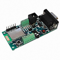
EVAL KIT BLUETOOTH VER2.0
Manufacturer
BlueRadios Inc
Type
Bluetooth V 2.0r
Datasheet
1.BR-EVAL2.0.pdf
(103 pages)
Specifications of BR-EVAL2.0
Frequency
2.4GHz
For Use With/related Products
Bluetooth
Lead Free Status / RoHS Status
Contains lead / RoHS non-compliant
Other names
822-1001


IMPORTANT NOTES:
Placing 3.3Vdc into the PIO’s while they are set as outputs will permanently damage the radio modules.
The failure mode is short across GND and VCC. When experimenting with the evaluation board use a
10KΩ series resistor when applying power to the terminal screw PIOs directly on the UART.
7173 S. Havana Street, Suite 600
PIO#7
6-Pin SPI
GND
MOSI
SPICK J5-3
SPICS J5-4
MISO
PWR
J4-1 GND
J4-2 RST Terminal Lug
(active LOW)
J4 pins 3,4,5,6
Reset Push Button Switch
(black) active
GND
3.3Vdc
Audio Jack (2.5mm)
Make sure to connect a common ground when using the external TX, RX inputs on the 0 – 3.3Vdc terminal
lug connector J4 of the evaluation board.
If you strobe PWR or GND to the top of the terminal lug screw heads make sure the screw is tighten down
or it may not connect the circuit (open circuit).
For a 3 wire DB-9 interface (tx, rx, gnd only) connect/short CTS to RTS, (J1-7&8). Factory default is
hardware flow control enabled CTS and RTS connected.
PIO’s are 0-3.3Vdc not 5 volt tolerant.
Disconnect RS-232 cable if using 3.3Vdc TX&RX input on J4 terminal lug connector. The Maxim RS-232
chip senses which data input is used between J1&J4 and it sometimes reacts to noise on the DB-9
connector if it is still connected while using J4.
Use standard pass through RS-232 serial cable. A null modem adaptor is not required.
Use a pull down resistor on “Factory Reset, PIO(4)” to ground if not in use to prevent inadvertent resetting
of parameters during initial module power up for your modules or disable this software feature using
ATSSW,0. Just grounding the signal will draw additional constant current. The remaining pins can float.
J5-2
J5-5
J5-6
J5-1
J8-1
J8-2
Low
NC
NC
NC
NC
NC
NC
NC
J1-5
NC
NC
J1-5
NC
www.BlueRadios.com
•
Englewood, CO 80112
J4-1
0-3.3Vdc only not
J4-2
RS-232 levels
SW1
J7
Copyright © 2002-2008
BlueRadios, Inc.
Page 12 of 103
•
Tel (303) 957-1003
Bluetooth connection on Channel 02
OUT→ 3.3Vdc (high state) Sink
current is 4mA max.
{point-to-point mode}
User assignable
{Multi-Point mode}
Bluetooth connection on Channel 03
OUT→ 3.3Vdc (high state) Sink
current is 4mA max.
Optional Ground
Reserved for BlueRadios
Reserved for BlueRadios
Reserved for BlueRadios
Reserved for BlueRadios
Optional External Power
Ground
Soft boots on RST radio pin
IN←GND
500 msec. to reboot
RTS,CTS, RXD,TXD connect directly
into the radio
Soft boots CPU on RST radio pin
IN←GND
500 msec. to reboot
Use to stimulate PIOs
GND (low)
Use to stimulate PIO’s 3.3Vdc (high)
Use with audio headset
BR-AT_COMMANDS-100 Rev. 3.6.2.1.4.0
strobe >5msec. Allow CPU
strobe >5msec. Allow CPU
•
sales@BlueRadios.com
Related parts for BR-EVAL2.0
Image
Part Number
Description
Manufacturer
Datasheet
Request
R

Part Number:
Description:
RF EVAL FOR BR-LE4.0 BLE
Manufacturer:
BlueRadios Inc
Datasheet:

Part Number:
Description:
EVAL BOARD BLUETOOTH VER2.0
Manufacturer:
BlueRadios Inc
Datasheet:

Part Number:
Description:
MODULE BT CLASS 1 W/ANT HCI FW
Manufacturer:
BlueRadios Inc
Datasheet:

Part Number:
Description:
TEST BOARD BLUESTAMP V2.0 18DIP
Manufacturer:
BlueRadios Inc
Datasheet:

Part Number:
Description:
USB NANO DONGLE BLUETOOTH VER2.1
Manufacturer:
BlueRadios Inc
Datasheet:

Part Number:
Description:
MODULE BT CLASS 2 ANT® HCI FW
Manufacturer:
BlueRadios Inc
Datasheet:
Part Number:
Description:
MODULE BLUETOOTH VER2.0 W/ANT
Manufacturer:
BlueRadios Inc
Datasheet:

Part Number:
Description:
MODULE BT CLASS 1 WO/ANT HCI FW
Manufacturer:
BlueRadios Inc
Datasheet:


Part Number:
Description:
MODULE BT CLASS 2 HCI NO ANT
Manufacturer:
BlueRadios Inc
Datasheet:

Part Number:
Description:
MODULE BLUETOOTH VER2.0 NO ANT
Manufacturer:
BlueRadios Inc
Datasheet:

Part Number:
Description:
MODULE BLUETOOTH V2.0 W/ANT®
Manufacturer:
BlueRadios Inc
Datasheet:

Part Number:
Description:
MODULE BLUESTAMP VER2.0 NO ANT
Manufacturer:
BlueRadios Inc
Datasheet:
