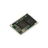
DVK-BTM411 Laird Technologies, DVK-BTM411 Datasheet - Page 45

DVK-BTM411
Manufacturer Part Number
DVK-BTM411
Description
BLUETOOTH EVAL BOARD BTM411
Manufacturer
Laird Technologies
Type
Transceiverr
Specifications of DVK-BTM411
Frequency
2.4GHz
Wireless Frequency
2.402 GHz to 2.48 GHz
Interface Type
UART
Data Rate
2.1 Mbps
Operating Voltage
3 V to 3.3 V
Antenna
Multilayer Ceramic Integrated
Operating Temperature Range
- 30 C to + 70 C
Output Power
4 dBm
Technology/ Type
Development Kit
For Use With/related Products
BTM411
Lead Free Status / RoHS Status
Lead free / RoHS Compliant
Lead Free Status / RoHS Status
Lead free / RoHS Compliant, Lead free / RoHS Compliant
Other names
DVK-BTM411
Available stocks
Company
Part Number
Manufacturer
Quantity
Price
Company:
Part Number:
DVK-BTM411-02
Manufacturer:
LAIRD
Quantity:
2
BTM410/411
Bluetooth
AT COMMAND SET
REFERENCE
45 www.lairdtech.com
®
AT Data Module
Register
S512
S514
S515
S516
S517
S518
S519
Deflt.
1
10
$001F00
$000000
20
8
500
Range
0..7
1..60
$000000..
$FFFFFF
0.. $2FFFFFF
2..61
0..255
100..3000
Description
Specify power up state.
When set to 0, AT+BTO is required to open the device for Blu-
etooth® activity.
When set to 1, it proceeds to a state as if AT+BTO was entered.
When set to 2, it will be discoverable only, similar to issuing
AT+BTQ.
When set to 3, it will be connectable but not discoverable e.g.
AT+BTG
When set to 4, it will be connectable and discoverable e.g.
AT+BTP.
When set to 5, it will be like 2, but all UART RX traffic is discarded
in absence of a connection while DSR is asserted. If DSR is not as-
serted, then it behaves exactly as per mode 2.
When set to 6, it will be like 3, but all UART RX traffic is discarded
in absence of a connection while DSR is asserted. If DSR is not as-
serted, then it behaves exactly as per mode 3.
When set to 7, it will be like 4, but all UART RX traffic is discarded
in absence of a connection while DSR is asserted. If DSR is not as-
serted, then it behaves exactly as per mode 4.
Note that by implication, a change to this can only be seen after a
power cycle AND if AT&W is
Pairing Timeout in seconds. This includes the time a host takes to
supply the PIN number when PIN? Messages are indicated.
Default Device Class Code. When queried, the value is always
printed as a hexadecimal number.
To change the device class of the module temporary and immedi-
ately without power cycle, use the command AT+BTC.
To change the device class of the module permanently, write the
new value to this S Register (ATS515=$<devclass
ting (AT&W) and initiate a power cycle (ATZ).
Default Device Class filter to be used with AT+BTI when it is not
explicitly specified. When queried the value is always printed as a
hex number.
The seventh most significant digit, can be 0,1 or 2, and is used to
specify the type of device class filter.
When 0, it specifies no filtering.
When 1, it specifies an AND mask and all 24 bits are relevant
When 2, it specifies a filter to look for devices with matching major
device class which occupies a 5 bit field from bits 8 to 12 inclusive
(assuming numbering starts at bit 0). All other 19 bits MUST be set
to 0.
Inquiry Length in units of seconds. This parameter is referenced by
the AT+BTI command.
Maximum number of responses from an inquiry request. This
parameter is reference by the AT+BTI command. If this number is
set too high, then AT+BTI will return ERROR 27. For a particular
firmware revision, determine the effective maximum value by trial
and error. That is, set to a high value, send AT+BTI and if ERROR
27 is returned, then retry with a smaller value.
This effective max value will remain unchanged for that particular
firmware build.
When S507>0, and in a connection, DSR can be used to change
from data to command state by de-asserting the DSR line for less
than the time specified in this register. This value is rounded down
to the nearest 100ms
hex
Laird Technologies
>), save the set-


