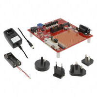
EM250-BBRD-R Ember, EM250-BBRD-R Datasheet - Page 101

EM250-BBRD-R
Manufacturer Part Number
EM250-BBRD-R
Description
EM250 BREAKOUT BOARD
Manufacturer
Ember
Type
Transceiver, 802.15.4r
Datasheet
1.EM250-RCM-R.pdf
(126 pages)
Specifications of EM250-BBRD-R
Frequency
2.4GHz
For Use With/related Products
EM250
Lead Free Status / RoHS Status
Lead free / RoHS Compliant
Other names
636-1024
- Current page: 101 of 126
- Download datasheet (3Mb)
5.6
Event Manager
The XAP2b core supports one IRQ and one wake-up input; however, the EM250 contains an advanced Event
Manager that takes IRQ and WAKE_UP signals from a variety of internal and external sources and provides
them to the XAP2b. The Event Manager allows for each event to be separately masked and cleared by the
CPU, and ensures that all events are serviced properly and promptly.
IRQ event sources include:
WAKE_UP event sources include:
All interrupt source signals (except level-triggered GPIO interrupt signals) are momentary pulses that are
guaranteed to be a single cycle of the main 12MHz clock. They will synchronously set the corresponding inter-
rupt source bit(s) within a set of hierarchically organized interrupt source register(s). The interrupt controller
merges these hierarchical interrupt sources into the single interrupt input to the CPU. Table 37 illustrates the
enable and configuration status of each event within the EM250.
The hierarchy has two levels of interrupt source and associated mask registers for fine control of interrupt
processing. The top-level
EM250. The second level is a set of
sub-function within their respective module. Some modules, like ADC, have no second level. For a top-level
event to actually interrupt the CPU, it must be enabled in the top-level
must additionally be enabled in their respective second-level
To clear (acknowledge) an interrupt, software must write a 1 into the corresponding bit of the interrupt's low-
est level
level, software must write a 1 into the
RXVALID second-level interrupt, software must write a 1 into the
INT_SC1FLAG
INT_FLAG
The interrupt source register bits are designed to remain set if the event reoccurs at the same moment the bit
is being cleared to acknowledge a prior occurrence.
If another enabled interrupt of the same type occurs before being acknowledged by the software ISR, it will
be lost because no counting or queuing is used. However, this condition is detected and stored in the top-level
INT_MISS
edged” in the same way as the
Event
Interrupt pin to CPU
Top: INT_FLAG
2
nd
: INT_periphFLAG
Timer events
GPIO events
SC1 and SC2 events
ADC
System-mode sources (MAC, Watchdog, etc.)
Timer events
GPIO events
SC1 and SC2 events
System-mode sources (MAC, Watchdog, etc.)
INT_periphFLAG
register would remain set, representing the “or” of all second-level-enabled SC1 interrupt events.
register to facilitate software detection of such problems. The
register. If there were other enabled SC1 interrupts pending, the top-level
INT_FLAG
register. For example, to acknowledge an ADC interrupt, which has no second
Table 37. Event Enable and Configuration Status
INT_FLAG
INT_periphFLAG
Configuration
INT_EN
INT_CFG
INT_periphCFG
and
INT_ADC
INT_CFG
register—by writing a 1 into the corresponding bit to be cleared.
Page 101
bit of the top-level
registers have one bit per major functional module of the
and
INT_periphCFG
INT_periphCFG
INT_SCRXVAL
INT_FLAG
INT_CFG
INT_MISS
registers that each have one bit per
registers.
register. To acknowledge a SC1
bit of the second-level
register. Second-level events
register is “acknowl-
INT_SC1
EM250
120-0082-000S
bit in the
Related parts for EM250-BBRD-R
Image
Part Number
Description
Manufacturer
Datasheet
Request
R

Part Number:
Description:
IC ZIGBEE SYSTEM-ON-CHIP 48-QFN
Manufacturer:
Ember
Datasheet:

Part Number:
Description:
KIT JUMP START FOR EM250
Manufacturer:
Ember
Datasheet:

Part Number:
Description:
KIT EVAL EM250 RF TEST
Manufacturer:
Ember
Datasheet:

Part Number:
Description:
EM250 RCM BOARD
Manufacturer:
Ember
Datasheet:

Part Number:
Description:
KIT DEV FOR EM250
Manufacturer:
Ember
Datasheet:

Part Number:
Description:
KIT DEV EMBER ZIGBEE W/PCWH
Manufacturer:
Custom Computer Services Inc (CCS)

Part Number:
Description:
PROGRAMMER USB FLASH EM250/260
Manufacturer:
Ember
Datasheet:

Part Number:
Description:
IC ZIGBEE SYSTEM-ON-CHIP 40-QFN
Manufacturer:
Ember
Datasheet:

Part Number:
Description:
IC RF TXRX ZIGBEE 128KB 48QFN
Manufacturer:
Ember
Datasheet:

Part Number:
Description:
IC RF TXRX ZIGBEE 192KB 48QFN
Manufacturer:
Ember
Datasheet:

Part Number:
Description:
INSIGHT ADAPTER FOR EM2XX
Manufacturer:
Ember
Datasheet:

Part Number:
Description:
IAR EWARM LICENCE FOR EM35X
Manufacturer:
Ember
Datasheet:

Part Number:
Description:
INSIGHT ADAPTER 3 FOR EM35X
Manufacturer:
Ember
Datasheet:

Part Number:
Description:
EM35X BREAKOUT BOARD
Manufacturer:
Ember
Datasheet:

Part Number:
Description:
EM260 RCM BOARD
Manufacturer:
Ember
Datasheet:


