DEMOBOARD-T7024PGM Atmel, DEMOBOARD-T7024PGM Datasheet - Page 7
DEMOBOARD-T7024PGM
Manufacturer Part Number
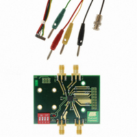
DEMOBOARD-T7024PGM
Description
BOARD DEMO FOR T7024PGM
Manufacturer
Atmel
Type
Bluetoothr
Specifications of DEMOBOARD-T7024PGM
Frequency
2.4GHz
Processor Series
T7024
Wireless Frequency
2.4 GHz
For Use With/related Products
T7024PGM
Lead Free Status / RoHS Status
Contains lead / RoHS non-compliant
Other names
DEMOBOARD-T7024-PGM


Design Guide T7024
For the design of the output matching circuit, an S-parameter test set or network ana-
lyzer may not be used. The measurement of the output matching with a network
analyzer results in wrong values since the measurement is done without RF input for the
output stage. Moreover, the output stage is sensitive to RF input power and bias, which
also changes with the RF input power. The output matching can only be designed using
a load pull setup, with which it is possible to measure the output power versus load
impedance. If a load pull setup is not available, the described matching with two capaci-
tors can be used to match the impedance of approximately 15
+ j17
at load 2.4 GHz
(at the output pins) for the PSSO20 package. The load impedance at the output pin 11
for the QFN20 package is approximately 22
+ j29
at 2.4 GHz.
The measured load pull data is summarized in Figure 19 on page 15 and Figure 20 on
page 15.
The output matching of the power amplifier includes loads which are used as harmonic
termination. In Figure 4 on page 3, these lines are called harmonic termination. The har-
monic termination consists of an open IC pin, which is internally connected to the PA
output. By using this harmonic terminations, the power added efficiency of the PA will be
increased. This effect, which influences the PA’s output impedance, is included in the
reported reference designs.
Please note, that it is important not only to design optimum input and output matching,
but also to design the right RF termination at the DC supplies to achieve optimum stabil-
ity against parasitic oscillations, output power and power added efficiency from the PA.
On the application board, all three stages of the amplifier are separated, allowing access
to each collector stage. Blocking capacitors are needed on each stage. In a final design
they can be combined to reduce space and costs.
The PA’s output power and the current consumption are regulated by the ramp pin,
which is also used to switch the PA to standby mode with a low quiescent current of typ-
ically below 10 µA. A ramp voltage between 1.3 V and 1.75 V is the usual operating
mode of the power amplifier. A higher ramping voltage results in a higher output power
of the PA. The operating point of 23 dBm output power is reached at approximately
1.75 V ramp signal.
The ramp control circuit for the T7024 is designed to operate with a control voltage as
input signal at the ramp input. However, it is also possible to use a current as an input
signal. This has advantages regarding the temperature behavior of the PA. The relation
of output power in dependence of ramp current is shown in Figure 8
The temperature compensation of the power amplifier should be done externally, e.g.,
with a processor with temperature sensor and D/A output which drives the ramp pin of
the PA. However, if this circuitry is not available, it is possible to use a solution for a sim-
ple temperature compensation, which is sufficient for most needs. This temperature
compensation uses the possibility to drive the ramp input with voltage or current simulta-
neously. Since the temperature behavior of the power amplifier is different for these two
modes, it is possible to select an optimum impedance to drive the power amplifier with a
specific ramp voltage and ramp current according to the desired output power.
A schematic for this simple temperature compensation is shown in Figure 9 on page 8.
The temperature compensation is optimized for different power levels in the range from
1 dBm to 23 dBm at the PA output. The resistors and reference voltages can be
adjusted according to different output power levels.
7
4549D–BLURF–06/04
Related parts for DEMOBOARD-T7024PGM
Image
Part Number
Description
Manufacturer
Datasheet
Request
R

Part Number:
Description:
BOARD DEMO FOR U4091BM
Manufacturer:
Atmel
Datasheet:


Part Number:
Description:
BOARD DEMO FOR U3600BM
Manufacturer:
Atmel
Datasheet:

Part Number:
Description:
BOARD DEMO FOR ATR2806
Manufacturer:
Atmel
Datasheet:
Part Number:
Description:
BOARD DEMO COM-I/Q MOD 1GHZ
Manufacturer:
Atmel
Datasheet:

Part Number:
Description:
Banana & Binding Post Connectors SINGLE PCB SOCK BLK
Manufacturer:
DEM Manufacturing
Datasheet:
Part Number:
Description:
Banana & Binding Post Connectors PLUG RED
Manufacturer:
DEM Manufacturing
Datasheet:
Part Number:
Description:
Banana & Binding Post Connectors SINGLE PCB SOCK RED
Manufacturer:
DEM Manufacturing
Datasheet:
Part Number:
Description:
DIN Connectors SOCKET NICKEL 8 PIN
Manufacturer:
DEM Manufacturing
Datasheet:
Part Number:
Description:
DIN Connectors PLUG NICKEL 3 PIN
Manufacturer:
DEM Manufacturing
Datasheet: