ATAVRRZ600 Atmel, ATAVRRZ600 Datasheet - Page 10
ATAVRRZ600
Manufacturer Part Number
ATAVRRZ600
Description
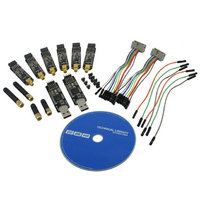
AVR TXRX EVAL KIT
Manufacturer
Atmel
Series
AVR®r
Type
Transceiver, Microcontrollerr
Specifications of ATAVRRZ600
Design Resources
RZ600 Radio Schematics RZ600 USB Adapter Schematics
Frequency
700MHz, 800MHz, 900MHz, 2.4GHz
Wireless Frequency
700 MHz to 2.4 GHz
Interface Type
USB
Antenna
SMA
For Use With/related Products
AT86RF
Lead Free Status / RoHS Status
Lead free / RoHS Compliant
Other names
ATRZ600
ATRZ600
ATRZ600


4.2.3 LEDs
4.2.4 Headers
10
AVR600
• 12MHz: The crystal is required as input to the internal PLL of the AT32UC3A3256
• 32kHz: Used as input source for the real time clock.
Figure 4-4 Clock Locations
Two LEDs are available connected to the AT32UC3A3256’s pins PX22 and PX41.
These are turned on by sinking current through the pin – logic low while acting as an
input.
Four headers are available on the processor board:
• 10-pin header (J101): Interface for the radio frequency board.
• Three pin header RF (J102 – not mounted): Auxiliary signals that can be
• JTAG Interface (J103 – not mounted): Standard Atmel JTAG header.
• Three pin header UART (J105 – not mounted): See Table 4-3 for pinout.
Table 4-2. J102 3-pin RF Auxiliary header
Pin
J102-1
J102-2
J102-3
Table 4-3. J105 3-pin UART header
Pin
J105-1
J105-2
J105-3
to generate the base frequency for the full and high speed USB mode.
patched in from the same three pin header on the radio frequency board. See
Table 4-2 for pinout.
USB interface
Name
Name
Test pin – AT86RF230
MCU:
AT32UC3A3256,
USB and RF Stacks
MCU oscillator
12MHz Xtal
A09-0831
USB card
Clock Output
Clock oscillator
32kHz Xtal
UART RX
UART TX
Realtime
ID Chip
GND
Serial comm
2-way sync
10 pin con
AT86RF230
Radio chip
A09-0489
RF card
16MHz Xtal
SMA connector
8293A-AVR-03/10
M01-SS2
Antenna
Related parts for ATAVRRZ600
Image
Part Number
Description
Manufacturer
Datasheet
Request
R

Part Number:
Description:
DEV KIT FOR AVR/AVR32
Manufacturer:
Atmel
Datasheet:

Part Number:
Description:
INTERVAL AND WIPE/WASH WIPER CONTROL IC WITH DELAY
Manufacturer:
ATMEL Corporation
Datasheet:
Part Number:
Description:
Low-Voltage Voice-Switched IC for Hands-Free Operation
Manufacturer:
ATMEL Corporation
Datasheet:
Part Number:
Description:
MONOLITHIC INTEGRATED FEATUREPHONE CIRCUIT
Manufacturer:
ATMEL Corporation
Datasheet:
Part Number:
Description:
AM-FM Receiver IC U4255BM-M
Manufacturer:
ATMEL Corporation
Datasheet:
Part Number:
Description:
Monolithic Integrated Feature Phone Circuit
Manufacturer:
ATMEL Corporation
Datasheet:
Part Number:
Description:
Multistandard Video-IF and Quasi Parallel Sound Processing
Manufacturer:
ATMEL Corporation
Datasheet:
Part Number:
Description:
High-performance EE PLD
Manufacturer:
ATMEL Corporation
Datasheet:
Part Number:
Description:
8-bit Flash Microcontroller
Manufacturer:
ATMEL Corporation
Datasheet:
Part Number:
Description:
2-Wire Serial EEPROM
Manufacturer:
ATMEL Corporation
Datasheet: