EVAL-ADF7020DB1 Analog Devices Inc, EVAL-ADF7020DB1 Datasheet - Page 9
EVAL-ADF7020DB1
Manufacturer Part Number
EVAL-ADF7020DB1
Description
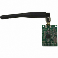
BOARD EVAL ADF7020 902-928MHZ
Manufacturer
Analog Devices Inc
Datasheet
1.EVAL-ADF7020DB2.pdf
(19 pages)
Specifications of EVAL-ADF7020DB1
Module/board Type
Evaluation Board
For Use With/related Products
ADF7020 928MHz
Lead Free Status / RoHS Status
Contains lead / RoHS non-compliant


Preliminary Technical Data
4.
5.
6.
7.
8.
Hit the Update All Button on the Software
Examine the output using the spectrum analyser. The
output should be locked to the programmed output
frequency and the output power should be approximately
+10dBm. There will be some error in the output frequency
due to error in the xtal, you should note this as it will be
useful for debuging the Rx section. You can adjust the
output power using the output power slide-bar in the
software.
Re-enter the Synth Settings sub-window and change the
output frequency and verify it covers your required
frequency range.
In-band Phase Noise is measured by narrowing the span
on the spectrum analyser to10kHz and turning Marker
Noise ON. A typical measurement for 0dBm output power
is –90dBc/Hz at 5kHz offset. ADISimPLL will help you
predict the expected phase noise numbers.
You can now apply modulation to the TxDATA pin and
monitor spurious, adjacent channel power and harmonic
levels.
e.
f.
Features Sub-window
Modulation Options
iii. Set LNA Bias = 800uA
iv. Set Mixer Linearity = Normal
vi. Hit Load Now and Return to Front
ii. Tx Data Invert ON(this will give high
ii. Using slide-bar change the power
v. Set PA bias to 9uA
i. Set crystal oscillator ON
i. Select OOK
Panel
level as RxTxData connected to GND).
setting to 43.
Rev. Pr C | Page 9 of 19
Test Procedure for the ADF7020/ADF7020-1 in Rx mode
Use a supply of 3V and the setup as shown in Figure 13. It is
important to note that the ADF7020/ADF7020-1 uses a low-IF
architecture where the IF is operating at 200kHz. This means
the LO frequency should be set to 200kHz below the incoming
RF frequency. The ADF7020 and ADF7020-1 software takes
care of this automatically for you.
9.
10. Using the ADF7020/ADF7020-1 software, setup the
11. Hit the Update All Button on the Software
12. Using the scope, probe the RxTxData pin and RxTxCLK.
Setup your signal generator to output an FSK signal at the
desired frequency, and –70dBm level. Select the data-rate
(9.6kbps) and deviation frequency(20kHz).
following Rx parameters:
They should be 3V p-p square-waves with frequencies of
4.8kHz and 9.6kHz respectively. Ensure that these square-
waves are triggered correctly and are not flickering.
a.
b.
c.
Figure 13. Evaluation board setup for Rx mode
Ensure Rx Mode is selected in Mode sub-window
In Synth Settings select the RF Frequency to the
signal generator Output frequency. The LO will
automatically be programmed to RF – 200kHz.
Modulation Options
iii. Set Data-Rate = 9.6 (kbps)
iv. Set Demod Type = Linear
vi. Click on AFC/Advanced button and
ii. Set Desired Deviation = 20kHz
v. Set IF Bandwidth = 150kHz
i. Select FSK Modulation
enable AFC. This will compensate for
errors in the crystal if the error at RF is
less than +/-50kHz. Step5 in the Tx
Mode setup will tell you the error.
EVAL-ADF7020DBX
Related parts for EVAL-ADF7020DB1
Image
Part Number
Description
Manufacturer
Datasheet
Request
R


Part Number:
Description:
BOARD EVAL FOR SI270X-A
Manufacturer:
Silicon Laboratories Inc
Datasheet:

Part Number:
Description:
BUCK CONV REF DESIGN KIT IP1201
Manufacturer:
International Rectifier
Datasheet:
Part Number:
Description:
BOARD DEMO SYNC DUAL BUCK CNVTER
Manufacturer:
International Rectifier
Datasheet:
Part Number:
Description:
BOARD DEMO SYNC BUCK CONVETER
Manufacturer:
International Rectifier
Datasheet:

Part Number:
Description:
EVALBOARD/EB Omnidirectional microphone - Analog
Manufacturer:
Analog Devices
Datasheet:
Part Number:
Description:
EVALBOARD/EB Omnidirectional microphone - Analog
Manufacturer:
Analog Devices
Datasheet:


Part Number:
Description:
BOARD EVAL LED DRIVER LT3756
Manufacturer:
Linear Technology
Datasheet:

Part Number:
Description:
BOARD EVAL FOR AD7741/7742
Manufacturer:
Analog Devices Inc
Datasheet:

Part Number:
Description:
±1.7g Dual-Axis IMEMS Accelerometer Evaluation Board
Manufacturer:
Analog Devices Inc
Datasheet:

Part Number:
Description:
IC MULTIPLIER ANALOG 8-SOIC T/R
Manufacturer:
Analog Devices Inc
Datasheet:

Part Number:
Description:
IC ANALOG MULTIPLIER 8-DIP
Manufacturer:
Analog Devices Inc
Datasheet:
Part Number:
Description:
IC ANALOG MULTIPLIER 8-SOIC
Manufacturer:
Analog Devices Inc
Datasheet:
Part Number:
Description:
IC ANALOG MULTIPLIER 8-DIP
Manufacturer:
Analog Devices Inc
Datasheet: