EVAL-ADF7020DB1 Analog Devices Inc, EVAL-ADF7020DB1 Datasheet - Page 11
EVAL-ADF7020DB1
Manufacturer Part Number
EVAL-ADF7020DB1
Description
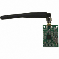
BOARD EVAL ADF7020 902-928MHZ
Manufacturer
Analog Devices Inc
Datasheet
1.EVAL-ADF7020DB2.pdf
(19 pages)
Specifications of EVAL-ADF7020DB1
Module/board Type
Evaluation Board
For Use With/related Products
ADF7020 928MHz
Lead Free Status / RoHS Status
Contains lead / RoHS non-compliant


Preliminary Technical Data
SETTING UP AN RF LINK USING THE ADF7020DBX
OR ADF7020-1DBX
The EVAL-ADF70XXMB2 boards which contain an embedded
microcontroller running a wireless network protocol is the
simplest way to setup and RF Link. If you are using the EVAL-
ADF70XXMB boards it is still possible to setup a basic link
using the antennas and software provided. The most straight-
forward way to do this is to have one board acting as a
dedicated Transmitter and one board as the dedicated Receiver.
This configuration is shown above. Note if you want to use one
board as a remote unit, you can connect a battery to the power-
block. If the battery voltage is greater than 3.6V you should use
the 3V regulator on the mother-board by connecting the jump
switch K3 to position A.
Tx Setup
Rx Setup
Connect the antenna to the Receiver and the PC cable to the
receiver mother-board
Follow steps 9. to 12. on Page8.
1.
2.
3.
4.
5.
1.
2.
Configure function generator to output a 3Vp-p
square-wave at 4.8kHz.
Follow steps 3a. to 3d. on Page 6.
Select FSK Modulation and set desired deviation to
20kHz and output power setting to 48.
Hit the Update All button and check the signal on a
Spectrum Analyszer to ensure this is outputting at the
correct frequency and level.
Connect the antenna provided and disconnect the PC
cable from the board.
The de-modulated signal should appear on the scope.
You should now be in a position to apply your own
modulation and de-modulate this correctly.
Rev. Pr C | Page 11 of 19
EVAL-ADF7020DBX
Related parts for EVAL-ADF7020DB1
Image
Part Number
Description
Manufacturer
Datasheet
Request
R


Part Number:
Description:
BOARD EVAL FOR SI270X-A
Manufacturer:
Silicon Laboratories Inc
Datasheet:

Part Number:
Description:
BUCK CONV REF DESIGN KIT IP1201
Manufacturer:
International Rectifier
Datasheet:
Part Number:
Description:
BOARD DEMO SYNC DUAL BUCK CNVTER
Manufacturer:
International Rectifier
Datasheet:
Part Number:
Description:
BOARD DEMO SYNC BUCK CONVETER
Manufacturer:
International Rectifier
Datasheet:

Part Number:
Description:
EVALBOARD/EB Omnidirectional microphone - Analog
Manufacturer:
Analog Devices
Datasheet:
Part Number:
Description:
EVALBOARD/EB Omnidirectional microphone - Analog
Manufacturer:
Analog Devices
Datasheet:


Part Number:
Description:
BOARD EVAL LED DRIVER LT3756
Manufacturer:
Linear Technology
Datasheet:

Part Number:
Description:
BOARD EVAL FOR AD7741/7742
Manufacturer:
Analog Devices Inc
Datasheet:

Part Number:
Description:
±1.7g Dual-Axis IMEMS Accelerometer Evaluation Board
Manufacturer:
Analog Devices Inc
Datasheet:

Part Number:
Description:
IC MULTIPLIER ANALOG 8-SOIC T/R
Manufacturer:
Analog Devices Inc
Datasheet:

Part Number:
Description:
IC ANALOG MULTIPLIER 8-DIP
Manufacturer:
Analog Devices Inc
Datasheet:
Part Number:
Description:
IC ANALOG MULTIPLIER 8-SOIC
Manufacturer:
Analog Devices Inc
Datasheet:
Part Number:
Description:
IC ANALOG MULTIPLIER 8-DIP
Manufacturer:
Analog Devices Inc
Datasheet: