TWR-MCF51JE Freescale Semiconductor, TWR-MCF51JE Datasheet - Page 34
TWR-MCF51JE
Manufacturer Part Number
TWR-MCF51JE
Description
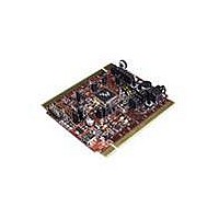
TOWER SYSTEM BOARD MCF51JE
Manufacturer
Freescale Semiconductor
Series
ColdFire®, Flexis™r
Type
MCUr
Specifications of TWR-MCF51JE
Contents
Board
Data Bus Width
32 bit
Interface Type
RS-232, RS-485, Ethernet, CAN, USB
Silicon Manufacturer
Freescale
Core Architecture
Coldfire
Core Sub-architecture
Coldfire V1
Silicon Core Number
MCF51J
Silicon Family Name
Flexis - MCF51JE
Rohs Compliant
Yes
For Use With/related Products
Freescale Tower System, MCF51JE
Lead Free Status / RoHS Status
Lead free / RoHS Compliant


Preliminary Electrical Characteristics
2
3
4
5
6
7
1-3
This specification applies to any time the FLL reference source or reference divider is changed, trim value is changed, DMX32 bit is
changed, DRS bit is changed, or changing from FLL disabled (BLPE, BLPI) to FLL enabled (FEI, FEE, FBE, FBI). If a
crystal/resonator is being used as the reference, this specification assumes it is already running.
This specification applies to any time the PLL VCO divider or reference divider is changed, or changing from PLL disabled (BLPE,
BLPI) to PLL enabled (PBE, PEE). If a crystal/resonator is being used as the reference, this specification assumes it is already
running.
Jitter is the average deviation from the programmed frequency measured over the specified interval at maximum f
Measurements are made with the device powered by filtered supplies and clocked by a stable external clock signal. Noise injected
into the FLL circuitry via V
625 ns represents 5 time quanta for CAN applications, under worst-case conditions of 8 MHz CAN bus clock, 1 Mbps CAN Bus
speed, and 8 time quanta per bit for bit time settings. 5 time quanta is the minimum time between a synchronization edge and the
sample point of a bit using 8 time quanta per bit.
Below D
already in lock, then the MCG may stay in lock.
Below D
#
1
2
3
4
5
Oscillator crystal or resonator
(EREFS = 1, ERCLKEN = 1)
Load capacitors
Feedback resistor
Series resistor — Low range
Series resistor — High range
lock
unl
minimum, the MCG will not exit lock if already in lock. Above D
minimum, the MCG is guaranteed to enter lock. Above D
DD
Table 18. XOSC (Temperature Range = –40 to 105
and V
SS
Characteristic
and variation in crystal oscillator frequency increase the C
Low range
(32 kHz to 38.4 kHz)
High range
(1 MHz to 16 MHz)
Low Gain (HGO = 0)
High Gain (HGO = 1)
• Low range (RANGE = 0)
• High range (RANGE = 1),
• FEE or FBE mode
• High range (RANGE = 1),
• High gain (HGO = 1),
• FBELP mode
• High range (RANGE = 1),
• Low power (HGO = 0),
• FBELP mode
• Low Gain (HGO = 0)
• High Gain (HGO = 1)
Preliminary — Subject to Change
≥ 8 MHz
4 MHz
1 MHz
2
lock
maximum, the MCG will not enter lock. But if the MCG is
unl
maximum, the MCG is guaranteed to exit lock.
Symbol
R
R
C
C
R
fhi
fhi
fhi
—
f
lo
S
S
1
2
F
°
C Ambient)
Jitter
Min
32
—
—
—
—
—
—
—
1
1
1
percentage for a given interval.
Typ
100
10
—
—
—
—
See Note
1
0
0
0
0
Freescale Semiconductor
1
BUS
.
3
Max
38.4
16
10
20
—
—
—
—
5
8
0
MHz
MHz
MHz
Unit
kHz
MΩ
kΩ
kΩ
Related parts for TWR-MCF51JE
Image
Part Number
Description
Manufacturer
Datasheet
Request
R

Part Number:
Description:
Power Management IC Development Tools Low-volt 3-phase MC
Manufacturer:
Freescale Semiconductor
Datasheet:
Part Number:
Description:
K53N512CMD100 TWR Module
Manufacturer:
Freescale Semiconductor
Datasheet:
Part Number:
Description:
TWR-K53N512 Dev Kit
Manufacturer:
Freescale Semiconductor
Datasheet:

Part Number:
Description:
CONV DC/DC TRI OUT 5,15,-15V
Manufacturer:
Murata Power Solutions Inc
Datasheet:

Part Number:
Description:
CONV DC/DC TRI OUT 5,12,-12V
Manufacturer:
Murata Power Solutions Inc
Datasheet:

Part Number:
Description:
CONV DC/DC TRI OUT 5,15,-15V
Manufacturer:
Murata Power Solutions Inc
Datasheet:

Part Number:
Description:
LCD MODULE FOR TWR SYSTEM
Manufacturer:
Freescale Semiconductor
Datasheet:

Part Number:
Description:
DC/DC TH 11W 5-5/12V Triple A
Manufacturer:
Murata Power Solutions Inc
Datasheet:


Part Number:
Description:
TOWER SYSTEM PROTO
Manufacturer:
Freescale Semiconductor
Datasheet:

Part Number:
Description:
TOWER ELEVATOR BOARDS HARDWARE
Manufacturer:
Freescale Semiconductor
Datasheet:

Part Number:
Description:
TOWER SERIAL I/O HARDWARE
Manufacturer:
Freescale Semiconductor
Datasheet:

Part Number:
Description:
TOWER SYSTEM BOARD MPC5125
Manufacturer:
Freescale Semiconductor
Datasheet: