TWR-K40X256 Freescale Semiconductor, TWR-K40X256 Datasheet - Page 9
TWR-K40X256
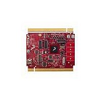
Manufacturer Part Number
TWR-K40X256
Description
TOWER SYSTEM BOARD K40X256
Manufacturer
Freescale Semiconductor
Series
Kinetisr
Type
MCUr
Specifications of TWR-K40X256
Contents
Board
Processor To Be Evaluated
K40
Data Bus Width
32 bit
Interface Type
USB, CAN, I2C, SPI, UART
Dimensions
3.5 in x 3.2 in
Operating Supply Voltage
1.71 V to 3.6 V
Silicon Manufacturer
Freescale
Core Architecture
ARM
Core Sub-architecture
Cortex - M4
Silicon Core Number
MK
Silicon Family Name
Kinetis - K40
Kit Contents
Board Only
Rohs Compliant
Yes
For Use With/related Products
Freescale Tower System, K40X256
Lead Free Status / RoHS Status
Lead free / RoHS Compliant


2.2 Clocking
The Kinetis MCUs start up from an internal digitally controlled oscillator (DCO). Software can enable
one or two external oscillators if desired. The external oscillator for the Multipurpose Clock Generator
(MCG) module can range from 32.768 KHz up to a 32 MHz crystal or ceramic resonator. The external
oscillator for the Real Time Clock (RTC) module accepts a 32.768 kHz crystal.
The clocking circuitry on the TWR-K40X256 is shown on sheet 4 of the schematics and in Figure 6. An
8.0 MHz ceramic resonator with built-in load capacitors is the default external source for the MCG
oscillator inputs (XTAL/EXTAL_MAIN). A 32.768 KHz crystal is connected to the RTC oscillator inputs by
default. There are optional resistors (not populated by default) to allow for the MCG oscillator inputs
to be routed from any one of the 8.0 MHz resonator, the 32.678 KHz crystal, or the clock input pin
CLKIN0 from the Primary Connector (pin B24). Table 1 shows the resistor settings for each of the MCG
oscillator input options.
USB full-speed/low-speed OTG/Host/Device controller with device charge detect
SPI, I
SD Host Controller (SDHC)
GPIO with pin interrupt support, DMA request capability, digital glitch filtering
Capacitive touch sensing inputs (TSI)
LCD display driver supporting 3V and 5V glass, configurable frontplane and backplane pins, and
segment failure detection
Debug interfaces: JTAG, cJTAG, SWD
Trace: TPIO, FPB, DWT, ITM, ETM, ETB
2
C (w/ SMBUS support), UART (w/ ISO7816 and IrDA), CAN, I
2
TWR-K40X256 Tower Module User's Manual
8
C31
C37
X3
8.00MHZ
8MHz_XTL
8MHz_EXTL
CLKIN0
DNP
DNP
18PF
18PF
Figure 6. External clock source circuitry
R89
0
Y 3
32.768KHz
32KHz_XTL
32KHz_EXTL
8MHz_XTL_R
R85
1.0M
R94
1.0M
DNP
R93
R91
R95
R97
R87
R86
R83
R84
DNP
DNP
DNP
DNP
0
0
0
0
0
0
0
0
2
S
Page 9 of 21
XTAL32_RTC
EXTAL32_RTC
XTAL_MAIN
EXTAL_MAIN
Related parts for TWR-K40X256
Image
Part Number
Description
Manufacturer
Datasheet
Request
R

Part Number:
Description:
TOWER SYSTEM KIT K40X256
Manufacturer:
Freescale Semiconductor
Datasheet:

Part Number:
Description:
K53N512CMD100 TWR Module
Manufacturer:
Freescale Semiconductor
Datasheet:
Part Number:
Description:
TWR-K53N512 Dev Kit
Manufacturer:
Freescale Semiconductor
Datasheet:

Part Number:
Description:
CONV DC/DC TRI OUT 5,15,-15V
Manufacturer:
Murata Power Solutions Inc
Datasheet:

Part Number:
Description:
CONV DC/DC TRI OUT 5,12,-12V
Manufacturer:
Murata Power Solutions Inc
Datasheet:

Part Number:
Description:
CONV DC/DC TRI OUT 5,15,-15V
Manufacturer:
Murata Power Solutions Inc
Datasheet:

Part Number:
Description:
LCD MODULE FOR TWR SYSTEM
Manufacturer:
Freescale Semiconductor
Datasheet:

Part Number:
Description:
DC/DC TH 11W 5-5/12V Triple A
Manufacturer:
Murata Power Solutions Inc
Datasheet:


Part Number:
Description:
TOWER SYSTEM PROTO
Manufacturer:
Freescale Semiconductor
Datasheet:

Part Number:
Description:
TOWER ELEVATOR BOARDS HARDWARE
Manufacturer:
Freescale Semiconductor
Datasheet:

Part Number:
Description:
TOWER SERIAL I/O HARDWARE
Manufacturer:
Freescale Semiconductor
Datasheet:

Part Number:
Description:
TOWER SYSTEM BOARD MPC5125
Manufacturer:
Freescale Semiconductor
Datasheet: