TWR-K40X256 Freescale Semiconductor, TWR-K40X256 Datasheet - Page 12
TWR-K40X256
Manufacturer Part Number
TWR-K40X256
Description
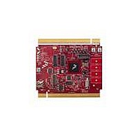
TOWER SYSTEM BOARD K40X256
Manufacturer
Freescale Semiconductor
Series
Kinetisr
Type
MCUr
Specifications of TWR-K40X256
Contents
Board
Processor To Be Evaluated
K40
Data Bus Width
32 bit
Interface Type
USB, CAN, I2C, SPI, UART
Dimensions
3.5 in x 3.2 in
Operating Supply Voltage
1.71 V to 3.6 V
Silicon Manufacturer
Freescale
Core Architecture
ARM
Core Sub-architecture
Cortex - M4
Silicon Core Number
MK
Silicon Family Name
Kinetis - K40
Kit Contents
Board Only
Rohs Compliant
Yes
For Use With/related Products
Freescale Tower System, K40X256
Lead Free Status / RoHS Status
Lead free / RoHS Compliant


Note: The port pins connected to the infrared interface (PTD6 and PTD7) are also connected to the
OSJTAG USB-to-serial bridge. Refer to Table 6 “I/O Connectors and Pin Usage Table” and Table 5
“TWR-K40X256 Jumper Table” for more information.
2.6 Accelerometer
An MMA7660 digital accelerometer is connected to the K40 MCU through an I2C interface and a
GPIO/IRQ signal. Refer to Table 6 “I/O Connectors and Pin Usage Table” for connection details.
2.7 Potentiometer, Pushbuttons, LEDs
The TWR-K40X256 features two pushbutton switches connected to GPIO/interrupt signals, one
pushbutton connected to the master reset signal, four capacitive touch pad electrodes, four user-
controllable LEDs, and a potentiometer connected to an ADC input signal. Refer to Table 6 “I/O
Connectors and Pin Usage Table” for information about which port pins are connected to these
features.
2.8 General Purpose Tower Plug-in (TWRPI) Socket
The TWR-K40X256 features a socket that can accept a variety of different Tower Plug-in modules
featuring sensors, RF transceivers, and more. The General Purpose TWRPI socket provides access to
I2C, SPI, IRQs, GPIOs, timers, analog conversion signals, TWRPI ID signals, reset, and voltage supplies.
The pinout for the TWRPI Socket is defined in Table 3.
Refer to Table 6 “I/O Connectors and Pin Usage Table” for the specific K40 pin connections to the
General Purpose TWRPI socket.
PTD7
TWR-K40X256 Tower Module User's Manual
CMT_IRO
P3V3
Default: no shunt
(Disable IRDA)
Figure 7. Infrared Port Implementation
Q3
QTLP610CPD
R24
1.54K
J6
IRDA_SEN
HDR 1X2 TH
R25
1.0K
IRDAJ
2
D3
QTLP610CIR
CMP0_IN0
C5
0.1UF
1
IRDAR
PTC6
R23
33
Page 12 of 21
Related parts for TWR-K40X256
Image
Part Number
Description
Manufacturer
Datasheet
Request
R

Part Number:
Description:
TOWER SYSTEM KIT K40X256
Manufacturer:
Freescale Semiconductor
Datasheet:

Part Number:
Description:
K53N512CMD100 TWR Module
Manufacturer:
Freescale Semiconductor
Datasheet:
Part Number:
Description:
TWR-K53N512 Dev Kit
Manufacturer:
Freescale Semiconductor
Datasheet:

Part Number:
Description:
CONV DC/DC TRI OUT 5,15,-15V
Manufacturer:
Murata Power Solutions Inc
Datasheet:

Part Number:
Description:
CONV DC/DC TRI OUT 5,12,-12V
Manufacturer:
Murata Power Solutions Inc
Datasheet:

Part Number:
Description:
CONV DC/DC TRI OUT 5,15,-15V
Manufacturer:
Murata Power Solutions Inc
Datasheet:

Part Number:
Description:
LCD MODULE FOR TWR SYSTEM
Manufacturer:
Freescale Semiconductor
Datasheet:

Part Number:
Description:
DC/DC TH 11W 5-5/12V Triple A
Manufacturer:
Murata Power Solutions Inc
Datasheet:


Part Number:
Description:
TOWER SYSTEM PROTO
Manufacturer:
Freescale Semiconductor
Datasheet:

Part Number:
Description:
TOWER ELEVATOR BOARDS HARDWARE
Manufacturer:
Freescale Semiconductor
Datasheet:

Part Number:
Description:
TOWER SERIAL I/O HARDWARE
Manufacturer:
Freescale Semiconductor
Datasheet:

Part Number:
Description:
TOWER SYSTEM BOARD MPC5125
Manufacturer:
Freescale Semiconductor
Datasheet: