TWR-MCF51MM Freescale Semiconductor, TWR-MCF51MM Datasheet - Page 4
TWR-MCF51MM
Manufacturer Part Number
TWR-MCF51MM
Description
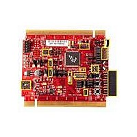
TOWER SYSTEM BOARD MCF51MM
Manufacturer
Freescale Semiconductor
Series
ColdFire®, Flexis™r
Type
MCUr
Specifications of TWR-MCF51MM
Contents
Board, 3 Modules, MED-EKG Kit, Cables, Documentation, DVD
Product
Microcontroller Modules
Data Bus Width
32 bit
Core Processor
MCF51MM
Clock Speed
32 KHz
Interface Type
RS232, RS485, CAN , USB
Flash
256 KB
Operating Supply Voltage
3.3 V
Silicon Manufacturer
Freescale
Core Architecture
Coldfire
Core Sub-architecture
Coldfire V1
Silicon Core Number
MCF51
Silicon Family Name
Flexis - MCF51MM
Rohs Compliant
Yes
For Use With/related Products
Freescale Tower System, MCF51MM
Lead Free Status / RoHS Status
Lead free / RoHS Compliant


2 Reference Documents
The documents listed below are available online. Refer to
latest revision of all Tower System documentation.
3 Hardware Features
This section provides more details about the features and functionality of the TWR-MCF51MM.
3.1
Two crystals are provided on the board for clocking the MCF51MM256 device:
3.2
The TWR-MCF51MM can be powered by the Open Source BDM (OSBDM) circuit via the Mini-B USB
connector when stand-alone. When assembled with the Tower System and the TWR-SER is configured
to run USB device mode (J16 pin 3 and 4 connected), the Mini-B USB connector is no longer used as a
power source and only used for OSBDM debugging purposes. In this case, the power will be supplied
from the Mini-B USB from the TWR-SER. Please plug in the Mini-B USB connector from TWE-SER before
plugging in the Mini-B USB connector from TWR-MCF51MM.
A standard USB A male to Mini-B male cable (provided) can be used to supply power from a USB host
or powered USB hub. Optionally, an AC to DC adapter with a USB A female receptacle (not provided)
can be used as the power source.
A jumper, J11, can be used to isolate the 3.3V supply from the microcontroller. This connection can be
used to measure the power usage of the MCF51MM256 microcontroller.
3.3
An on-board, MC9S08JM60 based OSBDM circuit provides a debug interface to the MCF51MM256. A
standard USB A male to Mini-B male cable (provided) can be used for debugging via the USB connector,
J17. Refer to Section 6 for information on other modes of operation of the OSBDM.
TWR-MCF51MM Schematics
TWR-MCF51MM Quick Start Guide
TWR-MCF51MM-KIT Lab Tutorial
MCF51MM256 Reference Manual
MCF51MM256 Data Sheet
AN3561, USB Bootloader for the MC9S08JM60
1. A 16 MHz crystal connected to XTAL2 and EXTAL2 for system clocking
2. A 32.768kHz crystal connected to XTAL1 and EXTAL1 for TOD usage
Clocking
System Power
Debug Interface
TWR-MCF51MM User Manual
http://www.freescale.com/tower
Page 4 of 12
for the
Related parts for TWR-MCF51MM
Image
Part Number
Description
Manufacturer
Datasheet
Request
R

Part Number:
Description:
Power Management IC Development Tools Low-volt 3-phase MC
Manufacturer:
Freescale Semiconductor
Datasheet:
Part Number:
Description:
K53N512CMD100 TWR Module
Manufacturer:
Freescale Semiconductor
Datasheet:
Part Number:
Description:
TWR-K53N512 Dev Kit
Manufacturer:
Freescale Semiconductor
Datasheet:

Part Number:
Description:
CONV DC/DC TRI OUT 5,15,-15V
Manufacturer:
Murata Power Solutions Inc
Datasheet:

Part Number:
Description:
CONV DC/DC TRI OUT 5,12,-12V
Manufacturer:
Murata Power Solutions Inc
Datasheet:

Part Number:
Description:
CONV DC/DC TRI OUT 5,15,-15V
Manufacturer:
Murata Power Solutions Inc
Datasheet:

Part Number:
Description:
LCD MODULE FOR TWR SYSTEM
Manufacturer:
Freescale Semiconductor
Datasheet:

Part Number:
Description:
DC/DC TH 11W 5-5/12V Triple A
Manufacturer:
Murata Power Solutions Inc
Datasheet:


Part Number:
Description:
TOWER SYSTEM PROTO
Manufacturer:
Freescale Semiconductor
Datasheet:

Part Number:
Description:
TOWER ELEVATOR BOARDS HARDWARE
Manufacturer:
Freescale Semiconductor
Datasheet:

Part Number:
Description:
TOWER SERIAL I/O HARDWARE
Manufacturer:
Freescale Semiconductor
Datasheet:

Part Number:
Description:
TOWER SYSTEM BOARD MPC5125
Manufacturer:
Freescale Semiconductor
Datasheet: