TWR-MCF51MM Freescale Semiconductor, TWR-MCF51MM Datasheet - Page 10
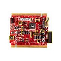
TWR-MCF51MM
Manufacturer Part Number
TWR-MCF51MM
Description
TOWER SYSTEM BOARD MCF51MM
Manufacturer
Freescale Semiconductor
Series
ColdFire®, Flexis™r
Type
MCUr
Specifications of TWR-MCF51MM
Contents
Board, 3 Modules, MED-EKG Kit, Cables, Documentation, DVD
Product
Microcontroller Modules
Data Bus Width
32 bit
Core Processor
MCF51MM
Clock Speed
32 KHz
Interface Type
RS232, RS485, CAN , USB
Flash
256 KB
Operating Supply Voltage
3.3 V
Silicon Manufacturer
Freescale
Core Architecture
Coldfire
Core Sub-architecture
Coldfire V1
Silicon Core Number
MCF51
Silicon Family Name
Flexis - MCF51MM
Rohs Compliant
Yes
For Use With/related Products
Freescale Tower System, MCF51MM
Lead Free Status / RoHS Status
Lead free / RoHS Compliant


5 Input/Output Connectors and Pin Usage Table
The following tables provide details on which MCF51MM256 pins are communicating with the TWR-
MCF51MM sensors, LEDs, switches and other I/O interfaces.
6 OSBDM
An on-board, MC9S08JM60 based OSBDM circuit provides a debug interface to the MCF51MM256.
The MC9S08JM60 is a USB-enabled microcontroller with an 8-bit HC9S08 core. The OSBDM circuit
provides a USB-to-debug interface that allows run-control and debugging of the MCF51MM256 target
device. The USB drivers required to communicate with the OSBDM are provided in development tools
such as Freescale CodeWarrior. When TWR-MCF51MM is used stand-alone, this single USB connection
can also be used for power.
6.1
The MC9S08JM60 device used in the OSBDM circuit is preprogrammed with OSBDM debugger
firmware and a USB Bootloader. The bootloader mode can be used to update the OSBDM debugger
firmware if an update becomes available. Jumper J12 determines which application will run following a
power-on reset. If the Bootloader Mode is chosen (jumper shunt on J12), the bootloader will be
Bootloader Mode For MC9S08JM60
Dip Switch
Push Button
LED
Accelerometer
MMA7361L
Potentiometer
RS232
ICL3232
NOTE: For more detail, please refer to TWR-MCF51MM schematics available in the
I/O Component
NOTE: LED1 to LED4 are labelled as D9 to D12 on the TWR-MCF51MM silkscreen.
TWR-MCF51MM
TWR-MCF51MM-KIT or on Freescale.com/tower.
SW3-1&4
SW3-2&3
SW1
SW2
SW4
LED1 (D9)
LED2(D10)
LED3(D11)
LED4(D12)
X_OUT
Y_OUT
Z_OUT
POT
232_RXD
232_TXD
I/O Label
Figure 6. I/O Connectors and Pin Usage Table
TWR-MCF51MM User Manual
Default
PTD1
PTA5
PTB1
PTC6
PTE4
PTE7
PTC2
PTC3
PTC4
PTA2
PTE6
PTE5
PTF2
PTF1
PTF0
USB_VBUSVLD
USB_ID
FB_RW
CMPP2
KBI2P1
CMPP3
KBI1P5
KBI1P6
KBI1P7
KBI1P1
/BLMS
FB_D7
Alt 1
RX2
TX2
-
MCF51MM256
USB_DM_DOWN TPM2CH0
USB_DP_DOWN
USB_SESSEND
USB_SESSVLD
PRACMPO
TPM2CH2
TPM2CH3
TPMCLK
SPSCK2
/RESET
CMPP0
Alt 2
/SS2
RX1
-
-
TPM2CH1
Page 10 of 12
ADP10
ADP6
ADP7
ADP8
ADP4
Alt 3
RX2
IRQ
TX2
-
-
-
-
-
Related parts for TWR-MCF51MM
Image
Part Number
Description
Manufacturer
Datasheet
Request
R

Part Number:
Description:
Power Management IC Development Tools Low-volt 3-phase MC
Manufacturer:
Freescale Semiconductor
Datasheet:
Part Number:
Description:
K53N512CMD100 TWR Module
Manufacturer:
Freescale Semiconductor
Datasheet:
Part Number:
Description:
TWR-K53N512 Dev Kit
Manufacturer:
Freescale Semiconductor
Datasheet:

Part Number:
Description:
CONV DC/DC TRI OUT 5,15,-15V
Manufacturer:
Murata Power Solutions Inc
Datasheet:

Part Number:
Description:
CONV DC/DC TRI OUT 5,12,-12V
Manufacturer:
Murata Power Solutions Inc
Datasheet:

Part Number:
Description:
CONV DC/DC TRI OUT 5,15,-15V
Manufacturer:
Murata Power Solutions Inc
Datasheet:

Part Number:
Description:
LCD MODULE FOR TWR SYSTEM
Manufacturer:
Freescale Semiconductor
Datasheet:

Part Number:
Description:
DC/DC TH 11W 5-5/12V Triple A
Manufacturer:
Murata Power Solutions Inc
Datasheet:


Part Number:
Description:
TOWER SYSTEM PROTO
Manufacturer:
Freescale Semiconductor
Datasheet:

Part Number:
Description:
TOWER ELEVATOR BOARDS HARDWARE
Manufacturer:
Freescale Semiconductor
Datasheet:

Part Number:
Description:
TOWER SERIAL I/O HARDWARE
Manufacturer:
Freescale Semiconductor
Datasheet:

Part Number:
Description:
TOWER SYSTEM BOARD MPC5125
Manufacturer:
Freescale Semiconductor
Datasheet: