78M6612-DB/OMU-RF Maxim Integrated Products, 78M6612-DB/OMU-RF Datasheet - Page 3
78M6612-DB/OMU-RF
Manufacturer Part Number
78M6612-DB/OMU-RF
Description
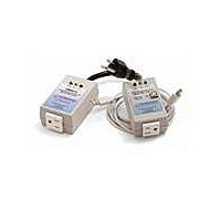
KIT DEMO OUTLET MEAS OMU1-S-RF
Manufacturer
Maxim Integrated Products
Datasheets
1.78M6612-IMF.pdf
(111 pages)
2.78M6612-EVM-1.pdf
(58 pages)
3.78M6612-DBOMU-RF.pdf
(41 pages)
4.78M6612-DBOMU-USB.pdf
(4 pages)
Specifications of 78M6612-DB/OMU-RF
Main Purpose
*
Embedded
*
Utilized Ic / Part
*
Primary Attributes
*
Secondary Attributes
*
Processor To Be Evaluated
78M6612
Data Bus Width
8 bit
Interface Type
UART
Lead Free Status / RoHS Status
Lead free / RoHS Compliant


UM_6612_016
1
2
3
4
5
6
7
Revision History .................................................................................................................................. 41
Rev. 1.2
Introduction.................................................................................................................................... 5
1.1
1.2
1.3
1.4
1.5
Installation ..................................................................................................................................... 7
2.1
2.2
2.3
2.4
2.5
2.6
Operating the Dashboard GUI ..................................................................................................... 21
3.1
3.2
3.3
3.4
3.5
3.6
3.7
3.8
3.9
3.10
3.11
3.12
3.13
3.14
3.15
3.16
3.17
3.18
Schematics, Bill of Materials and PCB Layouts ......................................................................... 33
4.1
4.2
4.3
4.4
4.5
Ordering Information ................................................................................................................... 41
Included Documentation ............................................................................................................. 41
Contact Information ..................................................................................................................... 41
Package Contents................................................................................................................. 5
System Requirements ........................................................................................................... 5
Safety and ESD Notes .......................................................................................................... 6
Firmware Demo Code Introduction ........................................................................................ 6
Testing the Demo Unit Prior to Shipping ................................................................................ 6
USB Driver Installation .......................................................................................................... 7
Basic Connection Setup ........................................................................................................ 8
2.2.1 Attaching the USB-OPTO Daughter Board to the OMU1-S-RF ..................................... 9
2.2.2 Attaching the UART-ISO Daughter Board to the OMU1-S-RF .................................... 10
2.2.3 Attaching a Customer-Supplied COM Module to the OMU1-S-RF .............................. 11
Confirm COM Port Mapping ................................................................................................ 12
Verify Serial Connection to the PC ...................................................................................... 13
NI™ RunTime Installation ................................................................................................... 15
Install LabWindows™ XP Pro Update ................................................................................. 18
Port Selection ..................................................................................................................... 21
Creating a Measurement Data Log File ............................................................................... 22
Selecting the Power Display Parameter............................................................................... 22
Selecting the Display Scales ............................................................................................... 23
Resetting the Min and Max Indicators to Their Current Values ............................................. 23
Begin Tracking Minimum and Maximum Conditions............................................................. 24
Selecting Outlet1 ................................................................................................................ 24
Selecting Wide Band or Narrow Band Measurement ........................................................... 25
Selecting the Sample Interval .............................................................................................. 25
Alarm Status ....................................................................................................................... 25
Neutral Voltage Alarm ......................................................................................................... 26
Line Frequency ................................................................................................................... 26
Accumulated Energy Usage and Expense Tracking ............................................................ 27
Displaying Narrowband and Wideband Values Simultaneously............................................ 27
Using the Parameter Graph ................................................................................................ 28
Setting Alarm Status Thresholds ......................................................................................... 28
Relay Configuration Controls............................................................................................... 29
Log File Import to Excel ...................................................................................................... 30
OMU1-S-RF Demo Board Schematics ................................................................................ 33
OMU1-S-RF Demo Board Bill of Materials ........................................................................... 35
OMU1-S-RF Board PCB Layouts ........................................................................................ 37
USB Daughter Board Schematic ......................................................................................... 39
UART-ISO Daughter Board Schematic ................................................................................ 40
Table of Contents
78M6612 OMU1-S-RF Demo Unit User Manual
3
Related parts for 78M6612-DB/OMU-RF
Image
Part Number
Description
Manufacturer
Datasheet
Request
R

Part Number:
Description:
KIT DEMO OUTLET MEASUREMENT OMU1
Manufacturer:
Maxim Integrated Products
Datasheet:

Part Number:
Description:
IC POWER MEASUREMENT AC 68-QFN
Manufacturer:
Maxim Integrated Products
Datasheet:

Part Number:
Description:
The Teridian™ 78M6612 is a highly integrated, single-phase, power and energy measurement and monitoring system-on-chip (SoC) that includes a 32-bit compute engine (CE), an MPU core, RTC, and flash
Manufacturer:
Maxim
Datasheet:

Part Number:
Description:
IC POWER MEASUREMENT AC 64-LQFP
Manufacturer:
Maxim Integrated Products
Datasheet:
Part Number:
Description:
IC POWER MEASUREMENT AC 68-QFN
Manufacturer:
Maxim Integrated Products
Datasheet:

Part Number:
Description:
IC POWER MEASUREMENT AC 64-LQFP
Manufacturer:
Maxim Integrated Products
Datasheet:
Part Number:
Description:
Current & Power Monitors & Regulators
Manufacturer:
Maxim Integrated Products
Datasheet:
Part Number:
Description:
Current & Power Monitors & Regulators 2 Out Sgl Phase Pwr & Energy Msrmt IC
Manufacturer:
Maxim Integrated Products
Datasheet:
Part Number:
Description:
Current & Power Monitors & Regulators
Manufacturer:
Maxim Integrated Products
Datasheet:
Part Number:
Description:
Current & Power Monitors & Regulators
Manufacturer:
Maxim Integrated Products
Datasheet:
Part Number:
Description:
Current & Power Monitors & Regulators
Manufacturer:
Maxim Integrated Products
Datasheet:
Part Number:
Description:
Current & Power Monitors & Regulators 2 Out Sgl Phase Pwr & Energy Msrmt IC
Manufacturer:
Maxim Integrated Products
Datasheet:
Part Number:
Description:
Current & Power Monitors & Regulators
Manufacturer:
Maxim Integrated Products
Datasheet:
Part Number:
Description:
Current & Power Monitors & Regulators
Manufacturer:
Maxim Integrated Products
Datasheet:
Part Number:
Description:
Current & Power Monitors & Regulators 2 Out Sgl Phase Pwr & Energy Msrmt IC
Manufacturer:
Maxim Integrated Products
Datasheet: