78M6612-DB/OMU-RF Maxim Integrated Products, 78M6612-DB/OMU-RF Datasheet
78M6612-DB/OMU-RF
Specifications of 78M6612-DB/OMU-RF


Related parts for 78M6612-DB/OMU-RF


78M6612-DB/OMU-RF Summary of contents
Page 1
Simplifying System Integration TM OMU1-S-RF Demo Unit User Manual February 18, 2010 Rev. 1.2 UM_6612_016 ...
Page 2
... OMU1-S-RF Demo Unit User Manual © 2010 Teridian Semiconductor Corporation. All rights reserved. Teridian Semiconductor Corporation is a registered trademark of Teridian Semiconductor Corporation. Simplifying System Integration is a trademark of Teridian Semiconductor Corporation. Microsoft, Windows, Vista, and Excel are registered trademarks of Microsoft Corporation. ...
Page 3
... OMU1-S-RF Demo Board Bill of Materials ........................................................................... 35 4.3 OMU1-S-RF Board PCB Layouts ........................................................................................ 37 4.4 USB Daughter Board Schematic ......................................................................................... 39 4.5 UART-ISO Daughter Board Schematic ................................................................................ 40 5 Ordering Information ................................................................................................................... 41 6 Included Documentation ............................................................................................................. 41 7 Contact Information ..................................................................................................................... 41 Revision History .................................................................................................................................. 41 Rev. 1.2 78M6612 OMU1-S-RF Demo Unit User Manual Table of Contents 3 ...
Page 4
... Figure 5: 78M6612 Evaluation Board PCB Top View .............................................................................. 37 Figure 6: 78M6612 Evaluation Board PCB Bottom View ......................................................................... 37 Figure 7: 78M6612 Evaluation Board Copper Top View ......................................................................... 38 Figure 8: 78M6612 Evaluation Board Copper Bottom View .................................................................... 38 Figure 9: USB Daughter Board Electrical Schematic .............................................................................. 39 Figure 10: UART-ISO Daughter Board Electrical Schematic ................................................................... 40 Tables Table 1: COM Port Setup Parameters ...
Page 5
... The Teridian Outlet Measurement Unit, Model OMU1-S-RF low-cost power monitor utilizing the Teridian 78M6612 SOC. The Teridian 78M6612 monitors the AC line voltages and load current, and controls switching of an internal load relay. The embedded firmware calculates the RMS line voltage and RMS load current, watts, VA, VAR and power factor. The real time data is transmitted for display ...
Page 6
... For information about the CLI, see the 6612_OMU_S2_URT_V1_13 Firmware Description Document. The OMU1-S-RF Demo Unit is shipped with Demo Code Revision 1.13 or later loaded in the 78M6612 chip and included on the CD. The code revision can be verified by entering the command >i via the command line interface. Firmware for the Demo Unit can be updated using either the Teridian TFP1 or an in-circuit emulator such as the Signum Systems™ ...
Page 7
... FTDI driver. Execute the ftdiClean.exe utility from the FTDI USB Driver and Utilities subdirectory. For FTDI driver support on other operating systems, please check FTDI’s website at (http://www.ftdichip.com/FTDrivers.htm). Rev. 1.2 78M6612 OMU1-S-RF Demo Unit User Manual 7 ...
Page 8
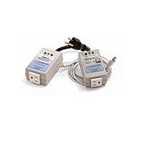
... OMU1-S-RF Demo Unit User Manual 2.2 Basic Connection Setup Figure 1 shows the basic connections of the OMU1-S-RF with the external equipment. The OMU1-S-RF is powered by an internal switch-mode power supply (SMPS) module and is not powered through the USB cable. The USB connection only provides the communications link between the host PC and the OMU1-S-RF ...
Page 9
... Attaching the USB-OPTO Daughter Board to the OMU1-S-RF Attach the USB-OPTO daughter board to the OMU1-S-RF for use with the supplied GUI. This hardware interface provides an easy way to explore the 78M6612 firmware features. The USB daughter board incorporates signal isolators to protect the connected PC. ...
Page 10
... Pin 2 TX (78M6612 output, Vout dependent on voltage at pin 1) Pin 3 RX (78M6612 input, Vin threshold dependent on voltage at pin 1) Pin 4 GND The UART-ISO daughter board does not support 1.8V signal levels. Do not attach external equipment to the OMU1-S-RF when using the UART-ISO. ...
Page 11
... The OMU1-S-RF UART cable does not support 1.8V signal levels. Do not attach external equipment to the OMU1-S-RF when using the UART cable necessary to attach test equipment, contact Teridian for instructions. Rev. 1.2 78M6612 OMU1-S-RF Demo Unit User Manual +3.3V (output, 100ma max) TX (78M6612 output, Vout: +3.3V/0V) RX (78M6612 input, Vin: +3.3V/0V) ...
Page 12
... OMU1-S-RF Demo Unit User Manual 2.3 Confirm COM Port Mapping 1. Launch the Control Panel and click on the System icon. 2. The System Properties screen appears. Click on the Hardware tab. Click on Device Manager. Under Ports (COM & LPT), look for the USB Serial Port assignment. ...
Page 13
... Communications HyperTerminal. The connection parameters are configured by selecting File Properties. The New Connection Properties menu appears. Select the appropriate COM port and click Configure. The COMn Properties menu appears. Rev. 1.2 78M6612 OMU1-S-RF Demo Unit User Manual Table 1: COM Port Setup Parameters 78M6612 38400 ...
Page 14
... OMU1-S-RF Demo Unit User Manual Note that port parameters can only be adjusted when the connection is not active. It may be necessary to click the Disconnect Button (shown in Disconnect Figure 2: HyperTerminal Window with the Disconnect Button disconnect the port. Figure 2 UM_6612_016 Rev. 1.2 ...
Page 15
... NI™ RunTime Installation The GUI Dashboard program is created using National Instruments LabVIEW™. The NI RunTime Engine must be installed first before launching the Dashboard GUI. 1. Open the LabWindows XP Installer directory on the CD. 2. Execute the setup.exe file. Rev. 1.2 78M6612 OMU1-S-RF Demo Unit User Manual 15 ...
Page 16
... OMU1-S-RF Demo Unit User Manual 3. Select the destination directory. 4. Accept the License Agreement. 16 UM_6612_016 Rev. 1.2 ...
Page 17
... UM_6612_016 5. Start the installation. 6. When the installation is complete, restart your computer. Rev. 1.2 78M6612 OMU1-S-RF Demo Unit User Manual 17 ...
Page 18
... OMU1-S-RF Demo Unit User Manual 2.6 Install LabWindows™ XP Pro Update Do not install LabWindows XP Pro Update on Win2k. 1. Launch the LabWindows XP Pro VISA Update.exe installation file on the CD. 2. Un-zip the file to the proper folder. 18 UM_6612_016 Rev. 1.2 ...
Page 19
... UM_6612_016 3. Start the installation. 4. Select the proper destination directories. 5. Accept the License Agreements. Rev. 1.2 78M6612 OMU1-S-RF Demo Unit User Manual 19 ...
Page 20
... OMU1-S-RF Demo Unit User Manual 6. The following screen appears. Click Next. 7. Click Finish. 8. Copy the OMU GUI V3p0.exe application file from the CD to your PC. 9. Restart your computer. 20 UM_6612_016 Rev. 1.2 ...
Page 21
... The Run and Stop buttons are located above the Teridian logo. Run If the OMU1 is disconnected from the USB cable, close and restart the GUI to re-establish the USB COM port connection. Rev. 1.2 78M6612 OMU1-S-RF Demo Unit User Manual Stop Section 2.2. COM Port ...
Page 22
... OMU1-S-RF Demo Unit User Manual 3.2 Creating a Measurement Data Log File Upon clicking the Run button, a File Write dialog box appears. The GUI stores retrieved measurement data to a file for post processing. Enter the desired subdirectory and file name. Click OK to launch the main GUI display ...
Page 23
... Min values) and the third row (the Max values). First Row – Current Conditions Second & Third Rows – Minimum & Maximum Rev. 1.2 78M6612 OMU1-S-RF Demo Unit User Manual Reset Min/Max Scale for Voltage, Watts and Current 23 ...
Page 24
... OMU1-S-RF Demo Unit User Manual 3.6 Begin Tracking Minimum and Maximum Conditions To begin tracking minimum and maximum conditions as they occur, click the Start Min/Max button. Minimum values will display in the second row and maximum values will display in the third row. ...
Page 25
... Sample Interval is set to 5 Seconds, Interval Cnt will count from 3.10 Alarm Status The Alarm Status indicator turns red if any Alarm Status Threshold is exceeded. See more information. Rev. 1.2 78M6612 OMU1-S-RF Demo Unit User Manual Wide Band or Narrow Band Sample Interval Interval Cnt Section 4.16 ...
Page 26
... OMU1-S-RF Demo Unit User Manual 3.11 Neutral Voltage Alarm The Neutral Voltage Alarm turns red when the Line and Neutral wires are reversed and Earth GND is connected. Earth GND must be connected for this function to operate properly. Line Earth GND 3.12 Line Frequency The Line Frequency indicator displays the existing line frequency ...
Page 27
... Enter Cost per KWh 3.14 Displaying Narrowband and Wideband Values Simultaneously Slide the horizontal scroll bar to the right to view both sets of data. Rev. 1.2 78M6612 OMU1-S-RF Demo Unit User Manual Vertical Scroll Bar Total Energy Total Cost Horizontal Scroll Bar 27 ...
Page 28
... OMU1-S-RF Demo Unit User Manual 3.15 Using the Parameter Graph Use the Parameter Graph to display sample size averages for a specified parameter and time scale. • Select the parameter to chart using the Select Parameter menu. • Select the time scale using the Select Time Scale menu. ...
Page 29
... GUI. The relay control button is located in the lower right hand corner of the main GUI control panel. A relay status indicator is located to the left of the control button. The relay status indicator and all other GUI indicators experience a 1-2 second update delay after clicking the relay control button. Rev. 1.2 78M6612 OMU1-S-RF Demo Unit User Manual Enter Value(s) Relay ...
Page 30
... OMU1-S-RF Demo Unit User Manual Advanced relay controls can be found by scrolling down to the bottom of the GUI. These are reserved for future use. Do not use with the OMU1-S-RF. 3.18 Log File Import to Excel The OMU1-S-RF measurement data can be graphed and post processed by importing its text data into various analysis programs ...
Page 31
... Change the Files of type to all Files(*.*). Then find your sub-directory and select your data log file. No changes required on the next dialog box, click Next. Uncheck Tab and then check Comma. Click Next to proceed. Rev. 1.2 78M6612 OMU1-S-RF Demo Unit User Manual 31 ...
Page 32
... OMU1-S-RF Demo Unit User Manual Select Text for Column data format. Click Finish to complete importing log file data. The log file text data can now be parsed using standard Excel formulas. 32 UM_6612_016 Rev. 1.2 ...
Page 33
... Non-Isolated MS 80-C330C104KCR SIP10BP UUDB MS 755-BP5045A SMPS MS 647-UUD1E221MNL All things ref erenced to V3P3 f or 78M6612 V3P3 connected to NEUTRAL f or Saf ety due to SMA GND shield Note: SMA GND shield is -3.3V relativ e to Neutral (Earth GND) V3P3 C1 1000pF C21 0603 ...
Page 34
... OMU1-S-RF Demo Unit User Manual Optional Reset Switch SW1 EVQ-PJX05M Panasonic R12 1K R13 1K C10 1000pF V3P3 R12 SW1 R13 0603 EP11 0603 V3P3 ICE inputs become LCD seg driv ers 1 when ICEE low RXTX J6 2 TCLK ICE 3 ERST SIP100P6 C14 ...
Page 35
... SOT23T MS 610-CMPTA63 ALZ 255-1446-ND 2512P MS 66-ULR25R004FLFTR 0603 P750YCT-ND 0603 MS 302-16.9K-RC 0603 MS 302-20K-RC 1206W MS 660- RN732BTTD1004B25 0 0603 MS 301-0-RC 78M6612 OMU1-S-RF Demo Unit User Manual Supplier Part Number Manufacturer 06035C102JAT2A AVX C0603C104K5RALTU KEMET TPSC106K025R0500 AVX 06035A101JAT2A AVX 06035A270JAT2A AVX 140-XRL450V10-RC Xicon C330C104KCR5TA KEMET ...
Page 36
... OMU1-S-RF Demo Unit User Manual Item Qty Reference Part 27 3 R14,R15,R16 470 28 1 R17 330 29 2 R18,R23 10K 30 1 R19 100 31 1 R20 10 1/ R22 10. R24 34 1 TP1 78M6612-68QFN 36 1 VR1 BP5045A 37 1 VR2 UCC284 32.768kHz 36 Digi-Key/Mouser PCB Footprint Part Number ...
Page 37
... UM_6612_016 4.3 OMU1-S-RF Board PCB Layouts Figure 5: 78M6612 Evaluation Board PCB Top View Rev. 1.2 78M6612 OMU1-S-RF Demo Unit User Manual Figure 6: 78M6612 Evaluation Board PCB Bottom View 37 ...
Page 38
... OMU1-S-RF Demo Unit User Manual Figure 7: 78M6612 Evaluation Board Copper Top View 38 Figure 8: 78M6612 Evaluation Board Copper Bottom View UM_6612_016 Rev. 1.2 ...
Page 39
... CBUS0 29 21 NC5 CBUS1 23 10 NC6 CBUS2 11 CBUS3 27 9 OSCI CBUS4 28 OSCO 16 U1 3V3OUT FT232QFN32 MS 895-FT232RQ FTQFN32 USBGND Figure 9: USB Daughter Board Electrical Schematic 78M6612 OMU1-S-RF Demo Unit User Manual TP2 HOST3V TPWW V3P3 UART1TX VOA VIA UART1RX VIB VOB ND1 ...
Page 40
... OMU1-S-RF Demo Unit User Manual 4.5 UART-ISO Daughter Board Schematic Figure 10: UART-ISO Daughter Board Electrical Schematic 40 UM_6612_016 Rev. 1.2 ...
Page 41
... Description 1.0 11/6/2009 First publication. 1.1 2/1/2010 Updated the schematics in Figure 3 and Figure 4. Updated the bill of materials in Table 2. 1.2 2/18/2010 In Table 2, added Supplier Part Number and Manufacturer columns to the Bill of Materials. Rev. 1.2 OMU1-S-RF Demo Unit User Manual Order Number 78M6612-DB/OMU-RF 41 ...