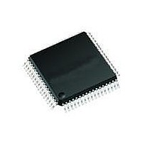
71M6511H-IGT/F Maxim Integrated Products, 71M6511H-IGT/F Datasheet - Page 64

71M6511H-IGT/F
Manufacturer Part Number
71M6511H-IGT/F
Description
IC ENERGY METER RESIDENT 64-LQFP
Manufacturer
Maxim Integrated Products
Datasheet
1.71M6511H-IGTF.pdf
(98 pages)
Specifications of 71M6511H-IGT/F
Processor Series
6511x
Core
80515
Data Bus Width
8 bit
Program Memory Type
Flash
Program Memory Size
64 KB
Data Ram Size
7 KB
Interface Type
I2C, SSI, UART
Maximum Clock Frequency
5 MHz
Number Of Programmable I/os
12
Number Of Timers
2
Operating Supply Voltage
3 V to 3.6 V
Maximum Operating Temperature
+ 85 C
Mounting Style
SMD/SMT
Package / Case
LQFP-64
3rd Party Development Tools
PK51, CA51, A51, ULINK2
Development Tools By Supplier
71M6511H-DB
Minimum Operating Temperature
- 40 C
On-chip Adc
22 bit Delta Sigma
Lead Free Status / RoHS Status
Lead free / RoHS Compliant
Available stocks
Company
Part Number
Manufacturer
Quantity
Price
Company:
Part Number:
71M6511H-IGT/F
Manufacturer:
PERICOM
Quantity:
1 200
Company:
Part Number:
71M6511H-IGT/F
Manufacturer:
Maxim Integrated
Quantity:
10 000
SSI_RDYEN
SSI_RDYPOL
SSI_BEG[7:0]
SSI_END[7:0]
SUM_CYCLES
[5:0]
TMUX[3:0]
RESERVED
TRIMSEL
TRIM
VERSION[7:0]
VREF_CAL
VREF_DIS
WD_RST
WD_OVF
Page: 64 of 98
A Maxim Integrated Products Brand
2070[1]
2070[0]
2071[7:0]
2072[7:0]
2001[5:0]
2000[3:0]
2005[7]
20FD
20FF
2006
2004[7]
2004[3]
SFR
E8[7]
2002[2]
© 2005–2010 Teridian Semiconductor Corporation
R/W
R/W
R/W
R/W
R/W
R/W
R/W
R/W
R/W
W
W
R
R
SRDY enable. If SSI_RDYEN and SSI_EN are high, the SEG6 pin is
configured as SRDY. Otherwise, it is an LCD driver.
SRDY polarity: 0: positive, 1: negative
The beginning and ending address of the transfer region of the CE
data memory. If the SSI is enabled, a block of words starting with
SSI_BEG and ending with SSI_END will be sent. SSI_END must be
larger than SSI_BEG. The maximum number of output words is limited
by the number of SSI clocks in a CE code pass—see FIR_LEN,
MUX_DIV, and SSI_10M.
Together w/ PRE_SAMPS, this value determines (for the CE) the
number of samples in one sum cycle between XFER interrupts.
Number of samples = PRE_SAMPS*SUM_CYCLES.
Selects one of 16 inputs for TMUXOUT.
0 – DGND (analog)
1 – IBIAS (analog)
2 – PLL_2.5V (analog)
3 – VBIAS (analog)
4 – RTM (Real time output from CE)
5 – WDTR_EN (Comparator 1 Output AND V1LT3)
6 – reserved
7 – reserved
8 – RXD (from Optical interface)
9 – MUX_SYNC (from MUX_CTRL)
A – CK_10M
B – CK_MPU
C – reserved for production test
D – RTCLK
E – CE_BUSY
F – XFER_BUSY
Must be zero.
Selects the temperature trim fuse to be read with the TRIM register
(TRIMM[2:0]: 4, TRIMBGA: 5, TRIMBGB: 6)
Contains TRIMBGA, TRIMBGB, or TRIMM[2:0] depending on the
value written to TRIMSEL. If TRIMBGB = 0 then the IC is a 6511 else
the IC is a 6511H.
The silicon revision number. This data sheet does not apply to
revisions < 000 0100.
Brings VREF out to the VREF pin. This feature is disabled when
VREF_DIS=1.
Disables the internal voltage reference.
Resets the WD timer. The WDT is reset when a 1 is written to this bit.
Only byte operations on the whole WDI register should be used.
The WD overflow status bit. This bit is set when the WD timer
overflows. It is powered by the VBAT pin and at boot-up will indicate if
the part is recovering from a WD overflow or a power fault. This bit
should be cleared by the MPU on boot-up. It is also automatically
cleared when RESETZ is low.
Single-Phase Energy Meter IC
71M6511/71M6511H
DATA SHEET
NOVEMBER 2010
V2.7


