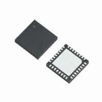
XR21V1412IL32-F Exar Corporation, XR21V1412IL32-F Datasheet - Page 15

XR21V1412IL32-F
Manufacturer Part Number
XR21V1412IL32-F
Description
IC UART FIFO USB DUAL 32QFN
Manufacturer
Exar Corporation
Type
USB UARTsr
Datasheet
1.XR21V1412IL32-F.pdf
(30 pages)
Specifications of XR21V1412IL32-F
Package / Case
32-VFQFN Exposed Pad
Features
*
Number Of Channels
2, DUART
Fifo's
128 Byte, 384 Byte
Protocol
USB 2.0
Voltage - Supply
2.97 V ~ 3.63 V
With Auto Flow Control
Yes
Mounting Type
Surface Mount
Maximum Operating Temperature
+ 85 C
Minimum Operating Temperature
- 40 C
Mounting Style
SMD/SMT
Supply Current
16 mA
Operating Supply Voltage
2.97 V to 3.63 V
No. Of Channels
2
Data Rate
12Mbps
Uart Features
Automatic Hardware And Software Flow Control, Half-Duplex Mode, Fractional Baud Rate Generator
Supply Voltage Range
2.97V To 3.63V
Rohs Compliant
Yes
Lead Free Status / RoHS Status
Lead free / RoHS Compliant
For Use With
1016-1301 - EVAL BOARD FOR XR21V1412IL
Lead Free Status / Rohs Status
Lead free / RoHS Compliant
Other names
1016-1302
Available stocks
Company
Part Number
Manufacturer
Quantity
Price
Company:
Part Number:
XR21V1412IL32-F
Manufacturer:
EXAR
Quantity:
1 800
Part Number:
XR21V1412IL32-F
Manufacturer:
EXAR/艾科嘉
Quantity:
20 000
REV. 1.1.0
The internal register set of the V1412 consists of 3 different blocks of registers: the UART Manager, UART
registers and UART miscellaneous registers. The UART Manager controls the TX and RX enables and FIFOs
of all UART channels. The UART registers configure and control the remaining UART channel functionality
with the exception of low latency mode, wide mode and custom interrupt packet enables in the UART custom
register block.
Registers are accessed only via the USB interface by the XR_SET_REG and XR_GET_REG commands listed
in
are given in
Enables the RX FIFO and TX FIFOs. For proper functionality, the UART TX and RX must be enabled in the
following order:
Writing a non-zero value to these registers resets the FIFOs.
A
3.0 REGISTER SET DESCRIPTION
3.1
3.1.1
3.1.2
DDRESS
0X10
0X18
0X19
0x1C
0x1D
0X11
Table
UART Manager Registers
FIFO_ENABLE_CHx = 0x1
UART_ENABLE = 0x3
FIFO_ENABLE_CHx = 0x3
4. The register address offsets are given in
FIFO_ENABLE_CHA
FIFO_ENABLE_CHB
RX_FIFO_RESET_CHA
RX_FIFO_RESET_CHB
TX_FIFO_RESET_CHA
TX_FIFO_RESET_CHB
FIFO_ENABLE Registers
RX_FIFO_RESET and TX_FIFO_RESET Registers
Table
R
EGISTER
5.
N
AME
B
Bit-7
Bit-7
Bit-7
Bit-7
T
IT
ABLE
0
0
-7
// Enable TX FIFO
// Enable TX and RX of that channel
// Enable RX FIFO
6: UART M
B
Bit-6
Bit-6
Bit-6
Bit-6
IT
0
0
-6
15
Table
ANAGER
B
Bit-5
Bit-5
Bit-5
Bit-5
IT
0
0
-5
6,
R
Table 7
EGISTERS
B
Bit-4
Bit-4
Bit-4
Bit-4
IT
0
0
-4
and
B
Bit-3
Bit-3
Bit-3
Bit-3
IT
0
0
Table
2-CH FULL-SPEED USB UART
-3
15, and the register blocks
B
Bit-2
Bit-2
Bit-2
Bit-2
IT
0
0
-2
XR21V1412
B
Bit-1
Bit-1
Bit-1
Bit-1
RX
RX
IT
-1
B
Bit-0
Bit-0
Bit-0
Bit-0
TX
TX
IT
-0


