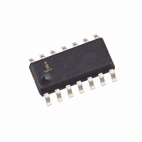
X5643S14-2.7 Intersil, X5643S14-2.7 Datasheet - Page 8

X5643S14-2.7
Manufacturer Part Number
X5643S14-2.7
Description
IC CPU SUPRV 64K EE RST LO SO14
Manufacturer
Intersil
Type
Simple Reset/Power-On Resetr
Datasheet
1.X5643P.pdf
(19 pages)
Specifications of X5643S14-2.7
Number Of Voltages Monitored
1
Output
Open Drain or Open Collector
Reset
Active Low
Reset Timeout
100 ms Minimum
Voltage - Threshold
2.63V
Operating Temperature
0°C ~ 70°C
Mounting Type
Surface Mount
Package / Case
14-SOIC (3.9mm Width), 14-SOL
Lead Free Status / RoHS Status
Contains lead / RoHS non-compliant
While the write is in progress following a status register or
EEPROM sequence, the status register may be read to
check the WIP bit. During this time the WIP bit will be high.
OPERATIONAL NOTES
The device powers-up in the following state:
– The device is in the low power standby state.
– A HIGH to LOW transition on CS is required to enter
– SO pin is high impedance.
Figure 6. Read Status Register Sequence
Figure 7. Write Enable Latch Sequence
an active state and receive an instruction.
SCK
CS
SO
SI
8
High Impedance
SCK
CS
SO
SI
0
1
Instruction
High Impedance
2
0
3
1
4
2
X5643, X5645
5
3
6
4
7
MSB
5
8
7
– The write enable latch is reset.
– The flag bit is reset.
– Reset signal is active for t
Data Protection
The following circuitry has been included to prevent
inadvertent writes:
– A WREN instruction must be issued to set the write
– CS must come HIGH at the proper clock count in
6
enable latch.
order to start a nonvolatile write cycle.
9
6
7
10 11 12 13 14
5
Data Out
4
3
2
1
0
PURST
.
July 18, 2005
FN8135.1


