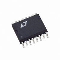
LTC695CSW-3.3#PBF Linear Technology, LTC695CSW-3.3#PBF Datasheet - Page 14

LTC695CSW-3.3#PBF
Manufacturer Part Number
LTC695CSW-3.3#PBF
Description
IC MPU SUPRVSRY CIRC 3.3V 16SOIC
Manufacturer
Linear Technology
Type
Simple Reset/Power-On Resetr
Datasheet
1.LTC694CS8-3.3PBF.pdf
(20 pages)
Specifications of LTC695CSW-3.3#PBF
Number Of Voltages Monitored
1
Output
Open Drain or Open Collector
Reset
Active High/Active Low
Reset Timeout
140 ms Minimum
Voltage - Threshold
2.9V
Operating Temperature
0°C ~ 70°C
Mounting Type
Surface Mount
Package / Case
16-SOIC (0.300", 7.5mm Width)
Lead Free Status / RoHS Status
Lead free / RoHS Compliant
Available stocks
Company
Part Number
Manufacturer
Quantity
Price
APPLICATIONS INFORMATION
LTC694-3.3/LTC695-3.3
WDI pin remains either high or low, reset pulses will be
issued every 1.6 seconds typically. The watchdog time
can be deactivated by floating the WDI pin. The timer
is also disabled when V
threshold or V
The LTC695-3.3 provides an additional output (Watchdog
Output, WDO) which goes low if the watchdog timer is
allowed to time out and remains low until set high by the
next transition on the WDI pin. WDO is also set high when
V
14
CC
falls below the reset voltage threshold or V
RESET
V
BATT
WDO
CC
WDI
= 3.3V
.
3.3V
3.3V
CC
4
4
3
3
1.6 SECOND WATCHDOG
INTERNAL OSCILLATOR
falls below the reset voltage
GND
V
GND
EXTERNAL CLOCK
V
CC
CC
LTC695-3.3
LTC695-3.3
t
1
Figure 11. Watchdog Timeout Period and Reset Active Time
OSC SEL
OSC SEL
OSC IN
OSC IN
8
7
8
7
Figure 12. Oscillator Configurations
t
FLOATING
OR HIGH
FLOATING
OR HIGH
2
BATT
.
t
1
t
t
t
1
2
3
= RESET ACTIVE TIME
= NORMAL WATCHDOG TIMEOUT PERIOD
= WATCHDOG TIMEOUT PERIOD IMMEDIATELY
AFTER A RESET
The LTC695-3.3 has two additional pins, OSC SEL and OSC
IN, which allow reset active time and watchdog timeout
period to be adjusted per Table 2. Several configurations
are shown in Figure 12.
OSC IN can be driven by an external clock signal or an
external capacitor can be connected between OSC IN and
GND when OSC SEL is forced low. In these configura-
tions, the nominal reset active time and watchdog timeout
period are determined by the number of clocks or set by
the formula in Table 2. When OSC SEL is high or floating,
3.3V
3.3V
t
3
4
3
4
3
EXTERNAL OSCILLATOR
INTERNAL OSCILLATOR
100ms WATCHDOG
V
GND
V
GND
CC
CC
LTC695-3.3
LTC695-3.3
OSC SEL
OSC SEL
OSC IN
OSC IN
8
7
8
7
FLOATING
OR HIGH
694/5-3.3 F12
694/5-3.3 F11
69453fb


