AD600JNZ Analog Devices Inc, AD600JNZ Datasheet - Page 2
AD600JNZ
Manufacturer Part Number
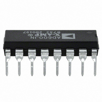
AD600JNZ
Description
IC AMP VGA DUAL LN 50MA 16DIP
Manufacturer
Analog Devices Inc
Series
X-AMP®r
Specifications of AD600JNZ
Amplifier Type
Variable Gain
Number Of Circuits
2
Slew Rate
275 V/µs
-3db Bandwidth
35MHz
Current - Input Bias
350nA
Current - Supply
11mA
Current - Output / Channel
50mA
Voltage - Supply, Single/dual (±)
±4.75 V ~ 5.25 V
Operating Temperature
0°C ~ 70°C
Mounting Type
Through Hole
Package / Case
16-DIP (0.300", 7.62mm)
No. Of Amplifiers
1
Bandwidth
35MHz
Gain Accuracy
1dB
No. Of Channels
1
Supply Voltage Range
± 4.75V To ± 5.25V
Amplifier Case Style
DIP
No. Of Pins
16
Operating Temperature Range
0°C To
Lead Free Status / RoHS Status
Lead free / RoHS Compliant
Output Type
-
Gain Bandwidth Product
-
Voltage - Input Offset
-
Lead Free Status / RoHS Status
Lead free / RoHS Compliant, Lead free / RoHS Compliant
Available stocks
Company
Part Number
Manufacturer
Quantity
Price

Part Number:
AD600JNZ
Manufacturer:
ADI/亚德诺
Quantity:
20 000


AD600/AD602
TABLE OF CONTENTS
Features .............................................................................................. 1
Applications....................................................................................... 1
General Description ......................................................................... 1
Functional Block Diagram .............................................................. 1
Revision History ............................................................................... 2
Specifications..................................................................................... 3
Absolute Maximum Ratings............................................................ 5
Pin Configuration and Function Descriptions............................. 6
Typical Performance Characteristics ............................................. 7
Theory of Operation ...................................................................... 10
REVISION HISTORY
1/06—Rev. D to Rev. E
Updated Format..................................................................Universal
Changes to Table 2............................................................................ 5
Changes to The Gain-Control Interface Section........................ 11
Updated Outline Dimensions ....................................................... 27
Changes to Ordering Guide .......................................................... 28
3/04—Rev. C to Rev. D
Changes to Specifications ................................................................ 2
Changes to Ordering Guide ............................................................ 3
Changes to Figure 3.......................................................................... 8
Changes to Figure 29...................................................................... 18
Updated Outline Dimensions ....................................................... 20
ESD Caution.................................................................................. 5
Noise Performance ..................................................................... 10
The Gain-Control Interface ...................................................... 11
Signal-Gating Inputs .................................................................. 11
Common-Mode Rejection ........................................................ 11
Achieving 80 dB Gain Range .................................................... 12
Sequential Mode (Maximum SNR) ......................................... 12
Parallel Mode (Simplest Gain-Control Interface).................. 13
Low Ripple Mode (Minimum Gain Error) ............................. 13
Rev. E | Page 2 of 28
Applications..................................................................................... 15
Outline Dimensions ....................................................................... 27
5/02—Rev. B to Rev. C
Changes to Specifications.................................................................2
Renumber Tables and TPCs...................................................Global
8/01—Rev. A to Rev. B
Changes to Accuracy Section of AD600A/AD602A column......2
Time-Gain Control (TGC) and Time-Variable
Gain (TVG) ................................................................................. 15
Increasing Output Drive............................................................ 15
Driving Capacitive Loads.......................................................... 15
Realizing Other Gain Ranges ................................................... 16
An Ultralow Noise VCA............................................................ 16
A Low Noise, 6 dB Preamplifier ............................................... 16
A Low Noise AGC Amplifier with 80 dB Gain Range .......... 17
A Wide Range, RMS-Linear dB Measurement System (2 MHz
AGC Amplifier with RMS Detector)....................................... 19
100 dB to 120 dB RMS Responding Constant Bandwidth
AGC Systems with High Accuracy dB Outputs ..................... 21
A 100 dB RMS/AGC System with Minimal Gain Error
(Parallel Gain with Offset) ........................................................ 22
A 120 dB RMS/AGC System with Optimal SNR
(Sequential Gain) ....................................................................... 23
Ordering Guide .......................................................................... 28
Related parts for AD600JNZ
Image
Part Number
Description
Manufacturer
Datasheet
Request
R

Part Number:
Description:
±1.7g Dual-Axis IMEMS Accelerometer Evaluation Board
Manufacturer:
Analog Devices Inc
Datasheet:

Part Number:
Description:
Inertial Sensor Evaluation System
Manufacturer:
Analog Devices Inc
Datasheet:
Part Number:
Description:
Manufacturer:
Analog Devices Inc
Datasheet:
Part Number:
Description:
Manufacturer:
Analog Devices Inc
Datasheet:
Part Number:
Description:
Manufacturer:
Analog Devices Inc
Datasheet:
Part Number:
Description:
Manufacturer:
Analog Devices Inc
Datasheet:
Part Number:
Description:
Manufacturer:
Analog Devices Inc
Datasheet:
Part Number:
Description:
Manufacturer:
Analog Devices Inc
Datasheet:
Part Number:
Description:
Manufacturer:
Analog Devices Inc
Datasheet:
Part Number:
Description:
Manufacturer:
Analog Devices Inc
Datasheet:
Part Number:
Description:
Manufacturer:
Analog Devices Inc
Datasheet:
Part Number:
Description:
Manufacturer:
Analog Devices Inc
Datasheet:
Part Number:
Description:
Manufacturer:
Analog Devices Inc
Datasheet: