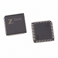
Z8F3201VN020EC00TR Zilog, Z8F3201VN020EC00TR Datasheet - Page 102

Z8F3201VN020EC00TR
Manufacturer Part Number
Z8F3201VN020EC00TR
Description
IC ENCORE MCU FLASH 32K 44PLCC
Manufacturer
Zilog
Series
Encore!®r
Datasheet
1.Z8F1601VN020EC.pdf
(246 pages)
Specifications of Z8F3201VN020EC00TR
Core Processor
Z8
Core Size
8-Bit
Speed
20MHz
Connectivity
I²C, IrDA, SPI, UART/USART
Peripherals
Brown-out Detect/Reset, DMA, POR, PWM, WDT
Number Of I /o
31
Program Memory Size
32KB (32K x 8)
Program Memory Type
FLASH
Ram Size
2K x 8
Voltage - Supply (vcc/vdd)
3 V ~ 3.6 V
Data Converters
A/D 8x10b
Oscillator Type
Internal
Operating Temperature
-40°C ~ 105°C
Package / Case
44-LCC (J-Lead)
Lead Free Status / RoHS Status
Contains lead / RoHS non-compliant
Eeprom Size
-
Other names
Z8F3201VN020EC00T
Available stocks
Company
Part Number
Manufacturer
Quantity
Price
- Current page: 102 of 246
- Download datasheet (2Mb)
Figure 70. UART Asynchronous Multiprocessor (9-bit) Mode Data Format
PS017610-0404
1
0
Idle State
of Line
Multiprocessor (9-bit) mode
6. Write to the UART Control 0 register to:
The UART and DMA are now configured for data reception and automatic data transfer to
the Register File. When a valid data byte is received by the UART the following occurs:
7. The UART notifies the DMA Controller that a data byte is available in the UART
8. The DMA Controller requests control of the system bus from the eZ8 CPU.
9. The eZ8 CPU acknowledges the bus request.
10. The DMA Controller transfers the data from the UART Receive Data register to
The UART and DMA can continue to transfer incoming data bytes without eZ8 CPU
intervention. When a UART error is detected, the UART Receiver interrupt is generated.
The associated interrupt service routine (ISR) should perform the following:
11. Check the UART Status 0 register to determine the source of the UART error or break
The UART has a Multiprocessor mode that uses an extra (9th) bit for selective communi-
cation when a number of processors share a common UART bus. In Multiprocessor (9-bit)
mode (also referred to as 9-Bit mode), the multiprocessor bit (MP) is transmitted immedi-
ately following the 8-bits of data and immediately preceding the STOP bit(s) as illustrated
in Figure 70. The character format is:
In Multiprocessor (9-bit) mode, parity is not an option as the Parity bit location (9th bit)
becomes the Multiprocessor control bit. The UART Control 1 and Status 1 registers pro-
vide multiprocessor (9-bit) mode control and status information.
Start
–
–
Receive Data register.
another location in RAM and then return bus control back to the eZ8 CPU.
condition and then respond appropriately.
Bit0
Set the receive enable bit (REN) to enable the UART for data reception
Enable parity, if desired, and select either even or odd parity.
lsb
Bit1
Bit2
Bit3
Data Field
Z8F640x/Z8F480x/Z8F320x/Z8F240x/Z8F160x
Bit4
Bit5
Bit6
msb
Bit7
MP
STOP Bit(s)
1
Z8 Encore!
2
UART
®
84
Related parts for Z8F3201VN020EC00TR
Image
Part Number
Description
Manufacturer
Datasheet
Request
R

Part Number:
Description:
Communication Controllers, ZILOG INTELLIGENT PERIPHERAL CONTROLLER (ZIP)
Manufacturer:
Zilog, Inc.
Datasheet:

Part Number:
Description:
KIT DEV FOR Z8 ENCORE 16K TO 64K
Manufacturer:
Zilog
Datasheet:

Part Number:
Description:
KIT DEV Z8 ENCORE XP 28-PIN
Manufacturer:
Zilog
Datasheet:

Part Number:
Description:
DEV KIT FOR Z8 ENCORE 8K/4K
Manufacturer:
Zilog
Datasheet:

Part Number:
Description:
KIT DEV Z8 ENCORE XP 28-PIN
Manufacturer:
Zilog
Datasheet:

Part Number:
Description:
DEV KIT FOR Z8 ENCORE 4K TO 8K
Manufacturer:
Zilog
Datasheet:

Part Number:
Description:
CMOS Z8 microcontroller. ROM 16 Kbytes, RAM 256 bytes, speed 16 MHz, 32 lines I/O, 3.0V to 5.5V
Manufacturer:
Zilog, Inc.
Datasheet:

Part Number:
Description:
Low-cost microcontroller. 512 bytes ROM, 61 bytes RAM, 8 MHz
Manufacturer:
Zilog, Inc.
Datasheet:

Part Number:
Description:
Z8 4K OTP Microcontroller
Manufacturer:
Zilog, Inc.
Datasheet:

Part Number:
Description:
CMOS SUPER8 ROMLESS MCU
Manufacturer:
Zilog, Inc.
Datasheet:

Part Number:
Description:
SL1866 CMOSZ8 OTP Microcontroller
Manufacturer:
Zilog, Inc.
Datasheet:

Part Number:
Description:
SL1866 CMOSZ8 OTP Microcontroller
Manufacturer:
Zilog, Inc.
Datasheet:

Part Number:
Description:
OTP (KB) = 1, RAM = 125, Speed = 12, I/O = 14, 8-bit Timers = 2, Comm Interfaces Other Features = Por, LV Protect, Voltage = 4.5-5.5V
Manufacturer:
Zilog, Inc.
Datasheet:

Part Number:
Description:
Manufacturer:
Zilog, Inc.
Datasheet:


