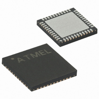
ATMEGA164P-15MT1 Atmel, ATMEGA164P-15MT1 Datasheet - Page 38

ATMEGA164P-15MT1
Manufacturer Part Number
ATMEGA164P-15MT1
Description
MCU AVR 16K FLASH 15MHZ 44-QFN
Manufacturer
Atmel
Series
AVR® ATmegar
Specifications of ATMEGA164P-15MT1
Core Processor
AVR
Core Size
8-Bit
Speed
16MHz
Connectivity
I²C, SPI, UART/USART
Peripherals
Brown-out Detect/Reset, POR, PWM, WDT
Number Of I /o
32
Program Memory Size
16KB (8K x 16)
Program Memory Type
FLASH
Eeprom Size
512 x 8
Ram Size
1K x 8
Voltage - Supply (vcc/vdd)
2.7 V ~ 5.5 V
Data Converters
A/D 8x10b
Oscillator Type
Internal
Operating Temperature
-40°C ~ 105°C
Package / Case
44-VQFN
Lead Free Status / RoHS Status
Lead free / RoHS Compliant
- Current page: 38 of 377
- Download datasheet (7Mb)
7.9
7.10
7.11
38
Timer/Counter Oscillator
Clock Output Buffer
System Clock Prescaler
ATmega164P/324P/644P
Table 7-15.
When applying an external clock, it is required to avoid sudden changes in the applied clock fre-
quency to ensure stable operation of the MCU. A variation in frequency of more than 2% from
one clock cycle to the next can lead to unpredictable behavior. If changes of more than 2% is
required, ensure that the MCU is kept in Reset during the changes.
Note that the System Clock Prescaler can be used to implement run-time changes of the internal
clock frequency while still ensuring stable operation. Refer to
38
ATmega164P/324P/644P uses the same type of crystal oscillator for Low-frequency Crystal
Oscillator and Timer/Counter Oscillator. See
details on the oscillator and crystal requirements.
The device can operate its Timer/Counter2 from an external 32.768 kHz watch crystal or a exter-
nal clock source. See
Applying an external clock source to TOSC1 can be done if EXTCLK in the ASSR Register is
written to logic one. See
uously compared with the counter value (TCNT2). A match can be used to generate an Output
Compare interrupt, or to generate a waveform output on the OC2B pin.” on page 158
description on selecting external clock as input instead of a 32.768 kHz watch crystal.
The device can output the system clock on the CLKO pin. To enable the output, the CKOUT
Fuse has to be programmed. This mode is suitable when the chip clock is used to drive other cir-
cuits on the system. The clock also will be output during reset, and the normal operation of I/O
pin will be overridden when the fuse is programmed. Any clock source, including the internal RC
Oscillator, can be selected when the clock is output on CLKO. If the System Clock Prescaler is
used, it is the divided system clock that is output.
The ATmega164P/324P/644P has a system clock prescaler, and the system clock can be
divided by setting the
to decrease the system clock frequency and the power consumption when the requirement for
processing power is low. This can be used with all clock source options, and it will affect the
clock frequency of the CPU and all synchronous peripherals. clk
are divided by a factor as shown in
BOD enabled
Fast rising power
Slowly rising power
for details.
Power Conditions
Start-up Times for the External Clock Selection
“CLKPR – Clock Prescale Register” on page
“Clock Source Connections” on page 31
“The Output Compare Register B contains an 8-bit value that is contin-
Power-down and Power-save
Start-up Time from
Table 7-16 on page
Reserved
6 CK
6 CK
6 CK
“Low Frequency Crystal Oscillator” on page 34
40.
Additional Delay from
“System Clock Prescaler” on page
Reset (V
for details.
14CK + 4.1 ms
I/O
14CK + 65 ms
40. This feature can be used
, clk
14CK
CC
ADC
= 5.0V)
, clk
CPU
, and clk
7674F–AVR–09/09
for further
SUT1..0
01
10
00
11
FLASH
for
Related parts for ATMEGA164P-15MT1
Image
Part Number
Description
Manufacturer
Datasheet
Request
R

Part Number:
Description:
Manufacturer:
Atmel Corporation
Datasheet:

Part Number:
Description:
Manufacturer:
Atmel Corporation
Datasheet:

Part Number:
Description:
IC MCU AVR 16K FLASH 44-TQFP
Manufacturer:
Atmel
Datasheet:

Part Number:
Description:
IC MCU AVR 16K FLASH 44-QFN
Manufacturer:
Atmel
Datasheet:

Part Number:
Description:
MCU AVR 16K FLASH 20MHZ 44-TQFP
Manufacturer:
Atmel
Datasheet:

Part Number:
Description:
MCU AVR 16KB FLASH 15MHZ 44TQFP
Manufacturer:
Atmel
Datasheet:

Part Number:
Description:
IC MCU AVR 16K FLASH 40-DIP
Manufacturer:
Atmel
Datasheet:

Part Number:
Description:
MCU AVR 16KB FLASH 20MHZ 44-VQFN
Manufacturer:
Atmel
Datasheet:

Part Number:
Description:
MCU AVR 16KB FLASH 20MHZ 44TQFP
Manufacturer:
Atmel
Datasheet:

Part Number:
Description:
MCU AVR 16K FLASH 20MHZ 44-QFN
Manufacturer:
Atmel
Datasheet:

Part Number:
Description:
MCU AVR 16K FLASH 20MHZ 40-PDIP
Manufacturer:
Atmel
Datasheet:

Part Number:
Description:
MCU AVR 16KB FLASH 15MHZ 44TQFP
Manufacturer:
Atmel
Datasheet:


