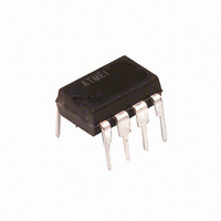
ATTINY15L-1PI Atmel, ATTINY15L-1PI Datasheet - Page 18

ATTINY15L-1PI
Manufacturer Part Number
ATTINY15L-1PI
Description
IC AVR MCU 1K FLASH 2.7V 8DIP
Manufacturer
Atmel
Series
AVR® ATtinyr
Specifications of ATTINY15L-1PI
Core Processor
AVR
Core Size
8-Bit
Speed
1.6MHz
Peripherals
Brown-out Detect/Reset, POR, PWM, WDT
Number Of I /o
6
Program Memory Size
1KB (512 x 16)
Program Memory Type
FLASH
Eeprom Size
64 x 8
Voltage - Supply (vcc/vdd)
2.7 V ~ 5.5 V
Data Converters
A/D 4x10b
Oscillator Type
Internal
Operating Temperature
-40°C ~ 85°C
Package / Case
8-DIP (0.300", 7.62mm)
Lead Free Status / RoHS Status
Contains lead / RoHS non-compliant
Ram Size
-
Connectivity
-
Available stocks
Company
Part Number
Manufacturer
Quantity
Price
Company:
Part Number:
ATTINY15L-1PI
Manufacturer:
AIMEL
Quantity:
5 510
Company:
Part Number:
ATTINY15L-1PI
Manufacturer:
VISHAY
Quantity:
5 510
Part Number:
ATTINY15L-1PI
Manufacturer:
ATMEL/爱特梅尔
Quantity:
20 000
MCU Status Register –
MCUSR
Internal Voltage
Reference
Voltage Reference Enable
Signals and Start-up Time
18
ATtiny15L
The MCU Status Register provides information on which reset source caused an MCU
Reset.
• Bit 7..4 – Res: Reserved Bits
These bits are reserved bits in the ATtiny15L and always read as zero.
• Bit 3 – WDRF: Watchdog Reset Flag
This bit is set (one) if a Watchdog Reset occurs. The bit is reset (zero) by a Power-on
Reset, or by writing a logical “0” to the flag.
• Bit 2 – BORF: Brown-out Reset Flag
This bit is set (one) if a Brown-out Reset occurs. The bit is reset (zero) by a Power-on
Reset, or by writing a logical “0” to the flag.
• Bit 1 – EXTRF: External Reset Flag
This bit is set (one) if a External Reset occurs. The bit is reset (zero) by a Power-on
Reset, or by writing a logical “0” to the flag.
• Bit 0 – PORF: Power-on Reset Flag
This bit is set (one) if a Power-on Reset occurs. The bit is reset (zero) by writing a logical
“0” to the flag.
To make use of the Reset Flags to identify a reset condition, the user should read and
then reset the MCUSR as early as possible in the program. If the register is cleared
before another reset occurs, the source of the reset can be found by examining the
Reset Flags.
ATtiny15L features an internal bandgap reference with a nominal voltage of 1.22V. This
reference is used for Brown-out Detection, and it can be used as an input to the Analog
Comparator. The 2.56V reference to the ADC is generated from the internal bandgap
reference.
The voltage reference has a start-up time that may influence the way it should be used.
The maximum start-up time is 10 µs. To save power, the reference is not always turned
on. The reference is on during the following situations:
1. When the BOD is enabled (by programming the BODEN Fuse).
2. When the bandgap reference is connected to the Analog Comparator (by setting
3. When the ADC is enabled.
Thus, when the BOD is not enabled, after setting the AINBG bit, the user must always
allow the reference to start-up before the output from the Analog Comparator is used.
The bandgap reference uses typically 10 µA, and to reduce power consumption in
Power-down mode, the user can avoid the three conditions above to ensure that the ref-
erence is turned off before entering Power-down mode.
Bit
$34
Read/Write
Initial Value
the AINBG bit in ACSR).
R
7
–
0
R
6
–
0
R
5
–
0
R
4
–
0
WDRF
R/W
3
BORF
R/W
2
See Bit Description
EXTRF
R/W
1
PORF
R/W
1187H–AVR–09/07
0
MCUSR


