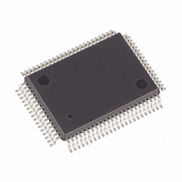
DS5003FPM-16+ Maxim Integrated Products, DS5003FPM-16+ Datasheet - Page 7

DS5003FPM-16+
Manufacturer Part Number
DS5003FPM-16+
Description
IC MICROPROCESSOR SECURE 80-MQFP
Manufacturer
Maxim Integrated Products
Series
DS500xr
Datasheet
1.DS5003-CS1.pdf
(24 pages)
Specifications of DS5003FPM-16+
Core Processor
8051
Core Size
8-Bit
Speed
16MHz
Connectivity
EBI/EMI, SIO, UART/USART
Peripherals
Power-Fail Reset, WDT
Number Of I /o
32
Program Memory Type
SRAM
Ram Size
256 x 8
Voltage - Supply (vcc/vdd)
4 V ~ 5.5 V
Oscillator Type
External
Operating Temperature
0°C ~ 70°C
Package / Case
80-MQFP, 80-PQFP
Processor Series
DS5003
Core
8051
Data Bus Width
8 bit
Program Memory Size
32 KB, 64 KB, 128 KB
Data Ram Size
32 KB, 64 KB, 128 KB
Interface Type
UART
Maximum Clock Frequency
16 MHz
Number Of Programmable I/os
32
Number Of Timers
2
Operating Supply Voltage
4.5 V to 5.5 V
Maximum Operating Temperature
+ 70 C
Mounting Style
SMD/SMT
3rd Party Development Tools
PK51, CA51, A51, ULINK2
Minimum Operating Temperature
0 C
Lead Free Status / RoHS Status
Lead free / RoHS Compliant
Eeprom Size
-
Program Memory Size
-
Data Converters
-
Lead Free Status / Rohs Status
Details
AC CHARACTERISTICS—PROG
(V
Note 1:
Note 2:
Note 3:
Note 4:
Note 5:
Note 6:
Note 7:
Note 8:
Note 9:
Note 10: V
Note 11: SDI is deglitched to prevent accidental destruction. The pulse must be longer than t
Note 12: Crystal startup time is the time required to get the mass of the crystal into vibrational motion from the time that power is
Figure 1. Expanded Data Memory Read Cycle
PROG Low to Active
PROG High to Inactive
CC
PORT 0
PORT 2
= 5V ±10%, T
ALE
RD
All voltages are referenced to ground.
Maximum operating I
XTAL2 disconnected; RST = Port 0 = V
Idle mode, I
disconnected; Port 0 = V
Stop mode, I
XTAL1 = V
Pin capacitance is measured with a test frequency: 1MHz, T
tion tested.
V
I
I
≤ 4.0; V
PF pin operation is specified with V
not guaranteed unless it is longer than t
first applied to the circuit until the first clock pulse is produced by the on-chip oscillator. The user should check with the
crystal vendor for a worst-case specification on this time.
CCO1
LI
CCO2
IHS
is the current drawn from the V
minimum is 2.0V or V
is the maximum average operating current that can be drawn from V
is measured with V
CC
A
PARAMETER
_______________________________________________________________________________________
= 0°C to +70°C.)
SS
≤ V
IDLE
STOP
.
BAT
, is measured with all output pins disconnected; XTAL1 driven with t
t
, is measured with all output pins disconnected; Port 0 = V
; V
ALPW
t
AVALL
SDI
(Rn OR DPL)
CC
A7–A0
should be ≤ V
is measured with all output pins disconnected; XTAL1 driven with t
CC
t
AVRDL
CCO
CC
, RST = MSEL = V
< V
, whichever is lower.
t
AVAAV
t
ALLRDL
LI
LI
BAT
and a maximum load of 10µA on V
t
input when V
AVDV
P2.7–P2.0 OR A15–A8 FROM DPH
ILS
CC
≥ 3.0V.
SPA
for I
, MSEL = V
t
ALLVD
.
Secure Microprocessor Chip
BAT
SS
t
.
RDLDV
CC
SYMBOL
max.
t
RDLAZ
t
t
= 0V and V
PRA
PRI
SS
t
RDPW
.
A
t
= +25°C. This specification is characterized but not produc-
RDHDV
DATA IN
CCO
is disconnected. Battery-backed mode is 2.5V ≤ V
CCO
t
RDHDZ
MIN
t
RDHALH
48
48
.
CCO
CC
; XTAL2 not connected; RST = MSEL =
in normal operation.
CLKR
SPR
to pass the deglitcher, but SDI is
, t
CLKF
CLKR
A7–A0
(PCL)
MAX
A15–A8 FROM PCH
, t
= 10ns, V
CLKF
= 10ns, V
IL
= 0.5V; XTAL2
INSTR
Clocks
Clocks
UNITS
IN
IL
= 0.5V;
BAT
7


