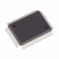
DS5003FPM-16+ Maxim Integrated Products, DS5003FPM-16+ Datasheet - Page 2

DS5003FPM-16+
Manufacturer Part Number
DS5003FPM-16+
Description
IC MICROPROCESSOR SECURE 80-MQFP
Manufacturer
Maxim Integrated Products
Series
DS500xr
Datasheet
1.DS5003-CS1.pdf
(24 pages)
Specifications of DS5003FPM-16+
Core Processor
8051
Core Size
8-Bit
Speed
16MHz
Connectivity
EBI/EMI, SIO, UART/USART
Peripherals
Power-Fail Reset, WDT
Number Of I /o
32
Program Memory Type
SRAM
Ram Size
256 x 8
Voltage - Supply (vcc/vdd)
4 V ~ 5.5 V
Oscillator Type
External
Operating Temperature
0°C ~ 70°C
Package / Case
80-MQFP, 80-PQFP
Processor Series
DS5003
Core
8051
Data Bus Width
8 bit
Program Memory Size
32 KB, 64 KB, 128 KB
Data Ram Size
32 KB, 64 KB, 128 KB
Interface Type
UART
Maximum Clock Frequency
16 MHz
Number Of Programmable I/os
32
Number Of Timers
2
Operating Supply Voltage
4.5 V to 5.5 V
Maximum Operating Temperature
+ 70 C
Mounting Style
SMD/SMT
3rd Party Development Tools
PK51, CA51, A51, ULINK2
Minimum Operating Temperature
0 C
Lead Free Status / RoHS Status
Lead free / RoHS Compliant
Eeprom Size
-
Program Memory Size
-
Data Converters
-
Lead Free Status / Rohs Status
Details
Secure Microprocessor Chip
ABSOLUTE MAXIMUM RATINGS
Voltage Range on Any Pin
Voltage Range on V
DC CHARACTERISTICS
(V
*Storage temperature is defined as the temperature of the device when V
are not battery backed and are undefined.
Note: The DS5003 adheres to all AC and DC electrical specifications published for the DS5002FP.
Stresses beyond those listed under “Absolute Maximum Ratings” may cause permanent damage to the device. These are stress ratings only, and functional
operation of the device at these or any other conditions beyond those indicated in the operational sections of the specifications is not implied. Exposure to
absolute maximum rating conditions for extended periods may affect device reliability.
2
Operating Voltage
Minimum Operating Voltage
Power-Fail Warning Voltage
Lithium Supply Voltage
Operating Current at 16MHz
Idle-Mode Current at 12MHz
Stop-Mode Current
Pin Capacitance
Output Supply Voltage (V
Output Supply Battery-Backed
Mode (V
PE2)
Output Supply Current (Note 7)
Lithium-Backed Quiescent
Current (Note 8)
Reset Trip Point in Stop Mode
Input Low Voltage
Input High Voltage
Input High Voltage
(RST, XTAL1, PROG)
Output Low Voltage at
I
OL
CC
Relative to Ground..................................-0.3V to (V
to Ground ..........................................................-0.3V to +6.0V
_______________________________________________________________________________________
= 1.6mA (Ports 1, 2, 3, PF)
= 5V ±10%, T
CCO
PARAMETER
, CE1–CE4, PE1,
A
CC
= 0°C to +70°C.)
Relative
CCO
)
SYMBOL
V
V
V
I
I
V
CCMIN
I
V
CCO1
STOP
V
V
V
CCO1
CCO2
C
I
IDLE
V
V
PFW
I
CC
OL1
CC
IH1
IH2
LI
LI
IN
IL
(Note 1)
0°C to +70°C (Note 1)
0°C to +70°C (Note 1)
(Note 1)
(Note 2)
0°C to +70°C (Note 3)
(Note 4)
(Note 5)
(Notes 1, 2)
0°C to +70°C (Notes 1, 6)
V
0°C to +70°C
BAT = 3.0V (0°C to +70°C) (Note 1)
BAT = 3.3V (0°C to +70°C) (Note 1)
(Note 1)
(Note 1)
(Note 1)
(Notes 1, 9)
CCO
CC
+ 0.5V)
= V
CC
- 0.45V
CONDITIONS
Operating Temperature Range.............................40°C to +85°C
Storage Temperature* .......................................-55°C to +125°C
Soldering Temperature...........................Refer to the IPC/JEDEC
CC
= 0V and V
LI
= 0V. In this state, the contents of SRAM
V
V
CCMIN
4.00
4.25
0.45
V
0.65
4.00
4.40
MIN
-0.3
2.5
2.0
3.5
CC
LI
-
-
TYP
4.12
4.37
0.15
5
J-STD-020 Specification.
V
V
MAX
+0.8
4.25
4.50
4.25
4.65
0.45
CC
CC
5.5
4.0
7.0
0.3
0.3
36
80
10
75
75
+
+
UNITS
mA
mA
mA
μA
pF
nA
V
V
V
V
V
V
V
V
V
V
V


